


CIRCUIT DESCRIPTION
6-28
March 1999
Part No. 001-2009-600
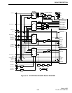
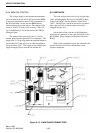
In operation, the power MOSFETs Q116, Q118
are on for approximately one-third of the period pro-
viding current to the primary side of T107. During
that time CR121 is forward conducting and charging
L101. When the MOSFETs are switched off, the mag-
netizing current of T107 continues to flow through
CR118, CR119. These diodes place 400V across the
transformer in opposite polarity that resets the trans-
former core. During the off period CR128 is free
wheeling and L101 is discharging. Transformer T107
provides the isolation between the low voltage and
high voltage sections.
The +26.5V pulse width modulator is peak cur-
rent mode controlled. This type of converter requires
current and voltage sense. T105, CR112, R125, R146
and C125 provide the current sense circuit. The volt-
age sense circuit is U109 and the associated circuitry
on the isolated side of the supply.
An opto-isolator is used to cross the boundary
from high to low voltage sections. In the event of an
over-voltage condition (>+32V) U115 and associated
components turn the power supply off. This shutdown
mechanism latches the power supply Off. The enable
line must be turned Off for 10 seconds for the power
supply to reset. T106 has a tap to provide current to
the optional battery back-up (Part No. 023-3-2000-
830). The +26.5V is available at the high current out-
put connector to the power supply and it also powers
the +15V, +5V and -5V converters through F102.
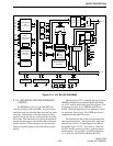
6.7.4 SYNCHRONIZING CIRCUITS
The +15V and +5V sections run at the same fre-
quency as the +26.5V pulse width modulator. In order
for a beat note not to be produced, a sync circuit is
used. If two converters are not synchronized, the dif-
ference frequency may show up at an undesired loca-
tion in the repeater.
Divider R151/R152 samples the output of the
main pulse width modulator. When Q116 and Q118
turn on, the output on U104A, pin 3 goes high. C138,
R176, CR122 along with U104B creates a very narrow
pulse on U104B, pin 6. Q110, Q111 and Q112 level
shift and buffer this pulse. When the narrow pulse is
presented to the timing capacitor of the +15V and +5V
converters, the cycle terminates and a new one starts.
This forces the +15V and +5V converters to run at the
same frequency and is slightly delayed from the
+26.5V converter.
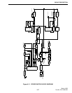
6.7.5 FAN AND THERMAL SHUTDOWN
The voltage supply to the thermal measurement
circuit is generated from transformer T101 and the
associated bridge rectifier consisting of CR101,
CR102, CR110 and CR111 and bulk storage capacitor
C101. This voltage is approximately +9V when the
AC voltage is at 120V AC.
NOTE: This DC voltage is dependent on the input AC
voltage.
U106 provides a very accurate +5V required for
proper operation of the temperature sense circuit. A
precision temperature sensor (U101) is mounted to the
+26.5V rectifier heatsink. The output of this sensor is
10 mV/°C with a ±1% accuracy. This voltage is
amplified by U110A with precision resistors R183/
R184 setting the gain.
The output of gain stage U110A is fed to the
computer interface via WO116 to monitor power sup-
ply temperature with the programmer. The output of
U110A, pin 3 is also connected to the thermal shut-
down circuit U110C, R135, R136, R137, R138 and
R139. If the heatsink temperature reaches 92°C
(198°F) the output of U110C, pin 8 goes high and sat-
urates Q103. When Q103 is turned on U107 is turned
off and the power supply turns off. The remote volt-
age is always present so when the heatsink tempera-
ture drops to 80°C (176°F) the power supply restarts.
The high temperature condition would only exist if the
fan was blocked or faulty.
The output of U110A, pin 1 also connects to the
fan controller. U110D with the associated resistors
provides a means to turn the fan on/off. Transistors
Q120/Q121 provide current gain and a voltage level
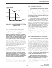
shift to run the fan. The fan turns on when the heat-
sink reaches approximately 45°C (113°F) and turns off
again when the temperature reaches 35°C (95°C). In
normal operation the fan turns on and off.