


ALIGNMENT AND TEST PROCEDURES
7-20
March 1999
Part No. 001-2009-600
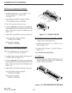
FSK Data Level Adjustment From Repeater
Separate Data Path (4-Wire) Optional Setting.
1. Set MAC S100 Sections 1, 4, 5, 8 OFF; 2, 3, 6, 7
ON; S101 Sections 2, 3, 4 OFF; 1 ON
(see Figure 7-15).
2. Adjust R240 on the MAC to obtain -16 dBm
(123 mV RMS) measured at J100/J103.
3. Press F2 to advance to the next screen.
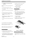
4. Connect a balanced AC Voltmeter with a 600 ohm
input impedance between balanced lines RXS+ and
RXS- of J2 located on the back of the Repeater (see
Figure 7-14).
5. Adjust R241 on the MAC for the type of line used.
Leased Line/Direct Connect (default)
-12 dBm (194 mV RMS)
Microwave/T1 (optional)
-28 dBm (31 mV RMS)
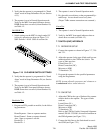
FSK Data Level Adjustment From Repeater
Data over Voice (2-Wire) Default Setting.
NOTE: This adjustment can only be done after
Voice Audio To Switch is completed.
1. Set MAC S100, all Sections OFF; S101 Sections 2,
3, 4 OFF; 1 ON (see Figure 7-15).
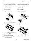
2. Connect a balanced AC Voltmeter with a 600 ohm
input impedance between balanced lines RXA+ and
RXA- of J2 located on the back of the Repeater (see
Figure 7-18).
3. Adjust R240 on the MAC for the type of line used.
Leased Line/Direct Connect (default)
-22 dBm (62 mV RMS)
Microwave/T1 (optional)
-38 dBm (10 mV RMS)
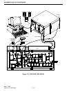
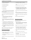
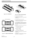
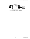
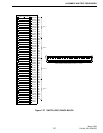
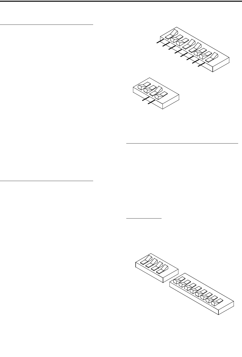
Figure 7-17 S100/S101 RS-232
RS-232 Data To And From Switch (RNT) (Optional)
These are the switch settings only.
1. Set MAC S100, Sections 2, 3, 6, 7 OFF; 1, 4, 5, 8
ON (see Figure 7-17).
2. Set MAC S101, Sections 1, 3, 4 OFF; 2 ON (see
Figure 7-17).
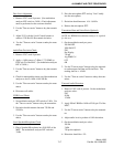
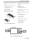
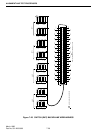
7.6.9 REPEATER OPERATION
New HSDB Test
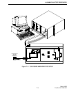
1. Switch settings on the MPC for RS-485 (new style)
operation are shown in Figure 7-18. S002 all Sec-
tion On. S003 all Section Off.
Figure 7-18 NEW HSDB SWITCH SETTINGS
O
N
2
1
8
7
6
5
4
3
O
N
2
1
4
3
R
X
S
-
(
G
N
D
)
R
X
S
-
R
X
S
+
(
A
U
D
I
O
)
R
X
S
+
(
F
S
K
)
R
X
S
-
(
G
N
D
)
TX
S
-
TX
S
+
(
A
U
D
I
O
)
T
X
S
+
(
FS
K
)
S
1
0
0
S
101
FS
K
T
X
S
+
O
N
O
N
S3
S2
2
1
8
7
6
5
4
3
2
1
4
3