


SERVICING
8-2
March 1999
Part No. 001-2009-600
8.2.2 TCXO MODULE
Check the signal at TCXO, pin 5. It should be
17.5 MHz for Y201 and Y401 at a level of approxi-
mately 3V P-P. If the TCXO is defective, it is not ser-
viceable and must be replaced with a new unit as
described in Section 8.1.5.
Measure the signal at pin 20 (Ref In) of the syn-
thesizer chip. It will be approximately 1V P-P. If the
signal is low here, the TCXO buffer circuit may be
defective.
8.2.3 VOLTAGE CONTROLLED OSCILLATOR
(VCO)
Check for VCO output signal with a high imped-
ance RF voltmeter. If there is no output signal, or if
the frequency is greatly off, the VCO is defective.
Next, monitor the signal level at pin 11 (F In) of
the synthesizer chip. If the signal is less than 100 mV
P-P, the VCO buffer is defective.
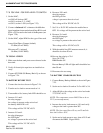
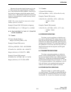
Lock Detector
When the VCO is locked on frequency, the wave-
form at pin 2 (Lock Det) should be as follows. When
the VCO is unlocked, the negative-going pulses
should be much wider than those shown in Figure 8-1.
If the lock detect circuit is operating properly, check
prescaler input pin 11 (F In).
The operation of the N and A counters can be
observed by monitoring pins 16 and 19. Pin 16 (f
V)
equals fin ÷ (64N+A) = 12.5 kHz if the synthesizer is
locked. Pin 9 is the modulus control signal.
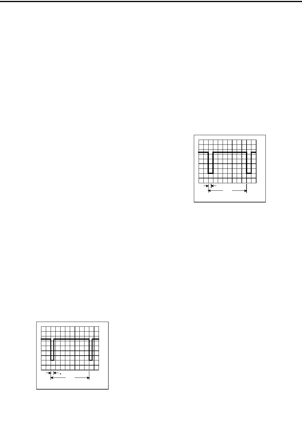
Figure 8-1 LOCK DETECT WAVEFORM
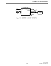
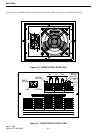
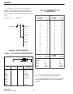
Modulus Control Signal
• The frequency of the modulus control signal on
TEST 1, pin 9 should be equal to the N counter out-
put frequency (either in or out of lock). When the
VCO is in lock, this frequency should be 12.5 kHz.
• The duty cycle of the modulus control signal deter-
mines the divide number of the prescaler. The duty
cycle (T1 ÷ T2) should be as follows:
T1 ÷ T2 = A Cntr Div No ÷ N Cntr Div No
T2 = 80 µs when locked.
Figure 8-2 MODULUS CONTROL WAVEFORM
If the modulus control signal is not correct, the
synthesizer may be defective or the logic may not be
programming the correct divide number.
8.2.4 INTERNAL PRESCALER
Checking Prescaler Divide Number
The prescaler divide number can be checked by
measuring the input and output frequencies. The pres-
caler divide number can be calculated as follows. (A
and N counter divide numbers are calculated as
described in Section 8.2.5.)
Prescaler Divide Number =
64 + (A Cntr Div No ÷ N Cntr Div No)
Example: Channel 200 (receive)
Prescaler Div No = 64 + (60 ÷ 1056) = 64.0568
0V
10us/DIV 2V/DIV
80us
50ns
T2
T1
0V
10us/DIV 2V/DIV