


LTR-Net PROGRAMMER
4-9
March 1999
Part No. 001-2009-600
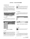
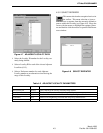
4.5.3 RF DATA
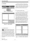
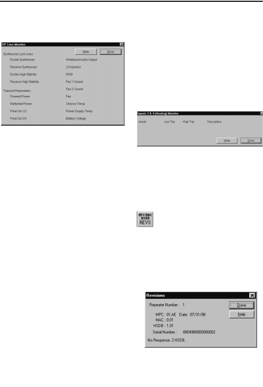
Figure 4-20 RF DATA
The RF Line Monitor window shows the state of
the lines (see Figure 4-19). These lines are monitored
by the A-D converter in the IAC. The normal values
for each line are defined as follows.
Synthesizer Lock Lines:
Exciter Synthesizer Yes, No
Receive Synthesizer Yes, No
Exciter High Stability Yes, No
Receive High Stability Yes, No
Wideband Audio Output approx. 200
LO Injection approx. 200
RSSI 20-150
Fan 1 Current 100-200, 0
Fan 2 Current 100-200, 0
Transmit Parameters:
Forward Power (Low Power 25-75 Watts
Forward Power (High Power) 75-175 Watts
Reflected Power 0-6 Watts
Final Out 1-2 (ratio) approx. equal
Final Out 3-4 (ratio) approx. equal
Chassis Temp 27°C-55°C
Fan On or Off
Power Supply Temp 22°C-45°C
Battery Voltage 21V-28V
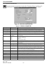
Values with no label are the actual A-D reading.
To calculate the voltage on the line, divide the value
by 51. Example: Value ÷ 51 = Volts. Any variation
from the above values may indicate a problem in that
area. Values in this window are relative measurements
only.
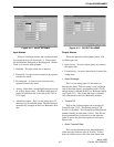
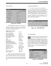
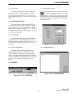
4.5.4 INPUT MONITOR
This window monitors the two Analog Input
lines. It is only used with the 4-Alarm Type IAC, and
only if Input 3, Input 4 or both are programmed for
"Analog". In addition to the actual or measured value,
the Low/High limit data are also displayed. These
limits are programmed in the "Edit -> Repeater Infor-
mation -> Input Alarms" screen (see Figure 4-13). If
one of these inputs is not programmed "Analog", the
data for that input is blanked.
Figure 4-21 INPUT MONITOR
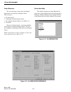
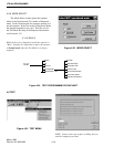
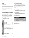
4.5.5 REVISIONS
This menu selection has an equivalent icon in
the toolbar. This menu selection or icon dis-
plays the current firmware revision informa-
tion for the MPC, MAC and HSDB. The format is R.V
(revision.version) for all modules. The MPC informa-
tion also includes the release date of the software and
the serial number of the repeater. The HSDB version in
Figure 4-22 is for J4, pins 5-6 connected in the MPC for
LTR-Net (J4, pins 3-4 connected in the MPC are for
standard LTR).
Figure 4-22 REVISIONS