


CIRCUIT DESCRIPTION
6-46
March 1999
Part No. 001-2009-600
6.12.19 J104 EXTERNAL SPEAKER
J104 provides an external speaker connection at
the repeater site for monitoring.
6.12.20 J105 WATCH DOG
J105 enables or disables the watchdog timer for
reset. Normal operating mode is P105 jumpering
J105, pins 2/3. This jumper should not be moved or
removed.
6.12.21 J106 TX DATA PATH
Jumpers P106 and P107 connect J106, pins 1-2
and 3-4 for external options that require the Tx Data
signal. Normal operation connects J106, pins 2-3 and
4-5.
6.12.22 A301 COMPANDOR CONNECTIONS
EP101 Expand In
EP102 Expand Out
EP103 Ground
EP104 Compress Out
EP105 Compress IN
EP106 +5V
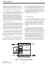
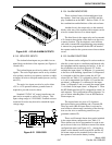
6.13 INTERFACE ALARM CARD
This card stores the information required to oper-
ate the alarms designated in the programming of the
repeater. Data is received on the address bus from the
MPC for the; operation to perform, the processor and
external memory, open and close relays on the outputs,
and receive alarm indications on the inputs. This
information is either routed to external devices or
alarm outputs can be wired to alarm inputs.
The Interface Alarm Card (IAC) contains 4-input
contacts and 4-output contacts. The 4- inputs can be
disabled, energized or de-energized. The 4-output
relays are dry contacts that have a 2A rating and can
be either normally open or normally closed.
The electromechanical relay outputs are com-
prised of eight SPDT (normally open) relays. The
relays are all open at power-on. Data to the relay is
latched by a write to the base address.
The IAC activates relays when alarm trigger
events occur. The IAC monitors for alarm activity in
the system and can set the various output relays as
defined by the user during programming. When an
external alarm is set it can be monitored from a remote
location. Refer to Section 4.7.2 for alarm program-
ming.
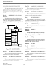
6.13.1 ALARM FORWARDING TO SWITCH
Repeater alarms are routed to the CIB (Channel
Interface Bus) to be detected by the Call Processor and
the System and Subscriber Manager.
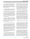
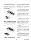
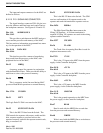
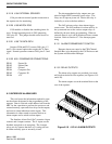
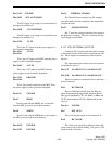
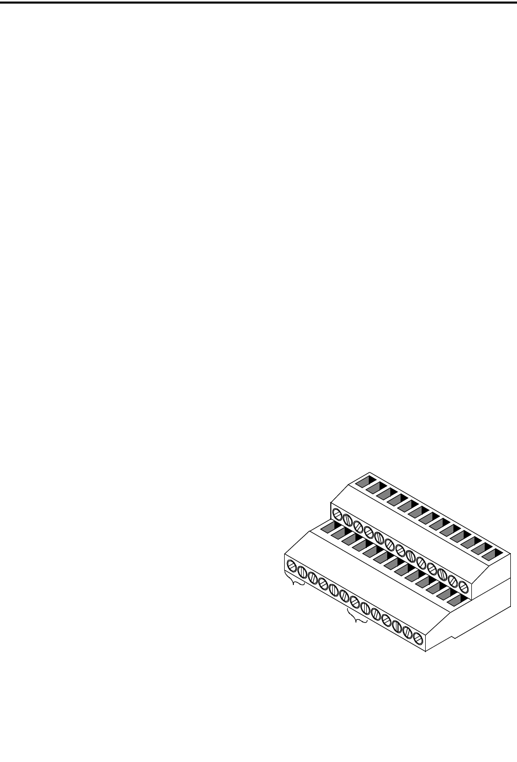
6.13.2 RELAY OUTPUTS
The alarm relay outputs are provided via a termi-
nal block on the back of the repeater (see Figures 6-19
and 6-20).
The alarm outputs are on the terminal block at the
rear of the repeater.
Figure 6-19 4 I/O J1 ALARM OUTPUTS
25
26
A
L
A
R
M
I
N
AL
A
R
M
O
U
T
I/0
13
1
2
4-
3-
3+
4+
3+
4-
3-
4
+
IA
C
41
EXTOUT1
COM
49
COM 50
T
X
D IN
RX
V
O
ICE
T
X
V
OI
CE
B
RX
WB
A
ND
COMM 6
S
Q
EN
E
X
T
REQ2
CO
M
1
7
S
YNC
I
N
TXD
O
UT
CO
M
53
CO
M
5
4
CO
M
55