


INSTALLATION
2-2
March 1999
Part No. 001-2009-600
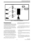
repeater or 6A for each 160W repeater and should be
protected by a circuit breaker. It is recommended that
all of the repeaters in a rack should not be on the same
breaker in order to provide one operational repeater in
the event a breaker trips. An AC surge protector is
recommended for all equipment.
Each Repeater requires an outlet, the receiver
multicoupler and OCXO drawer require one each, so
for a 5-channel system a minimum of 8 outlets are
required. An additional three should be added for test
equipment. The outlets must be within 3 feet of each
Repeater cabinet. Future system expansion should be
considered when electrical work is being planned for
the initial system.
The Viking VX Repeater power supply can be
equipped with an optional 24V DC back-up in the
event of AC power failure. Since the transmitter
remains on full power, if desired, the DC power source
must have a current capability of about 15A per 75W
repeater (25A per 160W repeater) or 75A for 5-75W
repeaters (125A for 5-160W repeaters). The multi-
coupler requires 0.5A and the OCXO drawer requires
1A for a total system requirement at 24V DC of 76.5A
for 75W repeaters (126.5A for 160W repeaters).
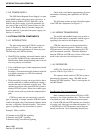
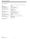
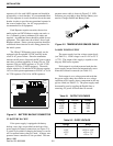
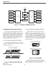
Figure 2-1 BATTERY BACKUP CONNECTOR
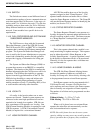
2.5 BATTERY BACKUP
If the power supply is equipped with battery
backup, screw lugs are provided on the front of the
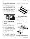
power supply for battery connections (see Figure 2-2).
A switch is provided for charging the battery or can be
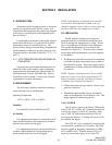
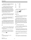
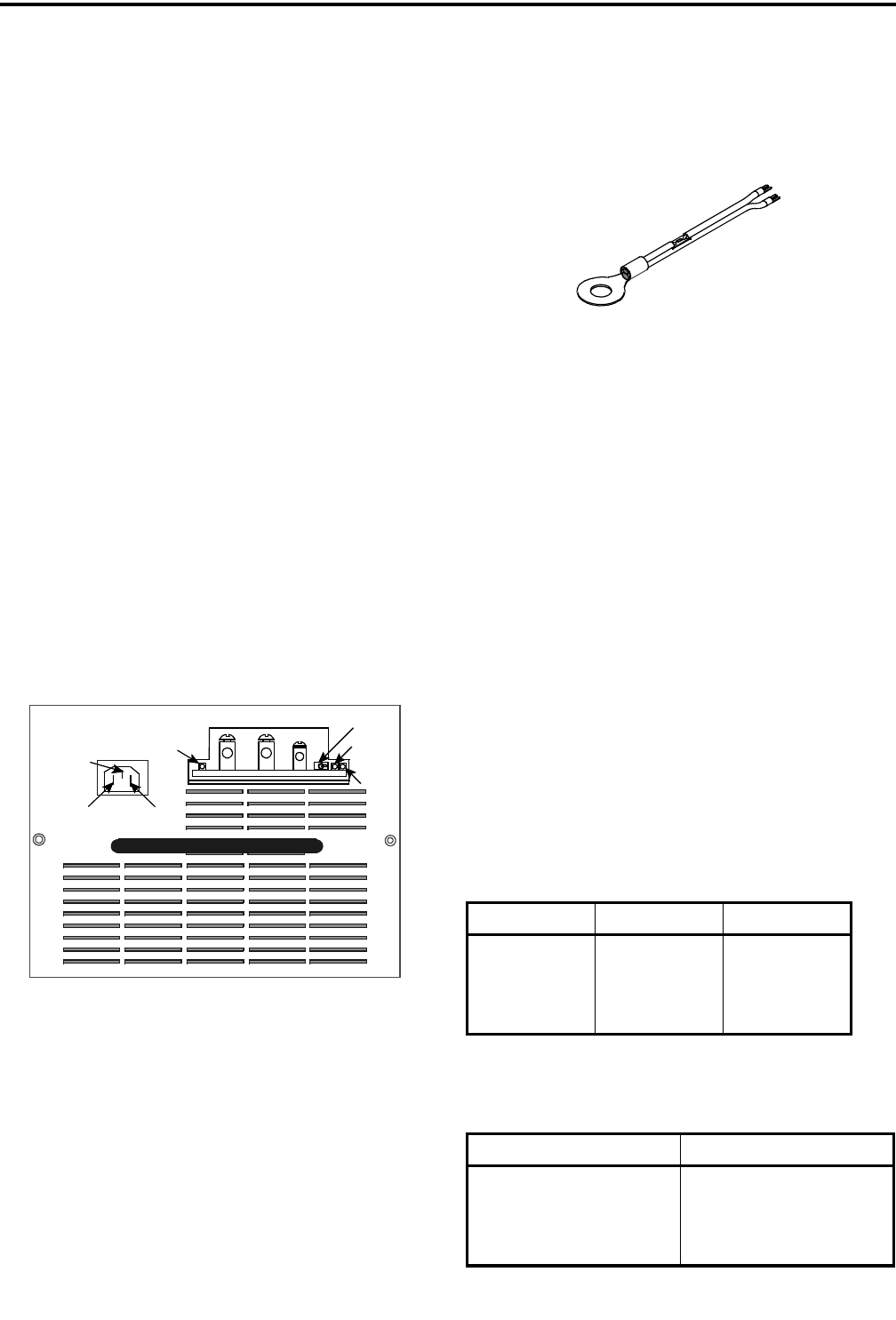
off if a separate battery charger is used. A battery tem-
perature sensor connection is also provided. The tem-
perature sensor cable is shown in Figure 2-2. LED
indicators are provided to show Reverse Battery con-
nection, Charger On/Off and Battery Fault.
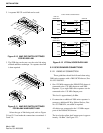
Figure 2-2 TEMPERATURE SENSOR CABLE
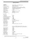
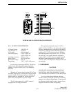
2.6 800W POWER SUPPLY
The power supply has four voltage output levels
(see Table 2-1). Each voltage is set to ±1% at +25°C
(+77°F). The output of this supply is capable or run-
ning any 2000 series repeater.
Each output is overload protected such that the
power supply current limits and automatically resets
when the overload is removed (see Table 2-1).
Each output is over voltage protected such that
the power supply shuts down when an over voltage
condition exists, usually when a component in the sup-
ply has failed (see Table 2-2). The power supply must
be manually reset by toggling the Enable Line or
removing AC power for more than 10 seconds.
B- B+ TEMP
ACTIVE
CHARGER
ON
CHARGER
FAULT
BATTERY
BATTERY
REVERSE
GROUND
EARTH
NEUTRAL
LINE
SWITCH
Table 2-1 OUTPUT VOLTAGES
Voltage Current Wattage
+26.5V 22A 583W
+15V 5A 75W
+5.2V 5A 26W
-5V 1A 5W
Table 2-2 OVER VOLTAGE
Voltage Range
+26.5V +32V to +33V
+15V +16V to +18V
+5.2V +6V to +7V
-5V -6V to -7V
BATTERY
TEMP
TERMINAL
NEGATIVE
GND
BLK
WHT