


LTR-Net PROGRAMMER
4-2
March 1999
Part No. 001-2009-600
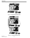
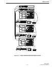
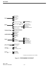
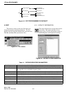
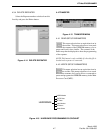
Figure 4-4 EDIT PROGRAMMING FLOWCHART
Define Repeaters
Adjacent Locality Data
Edit Parameters
General Parameters
Select Repeater
Repeater Information
EDIT
Locality Information
Delete Repeater
Input Alarms
Output Alarms
Alarm Cross Reference
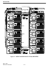
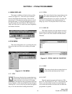
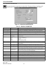
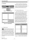
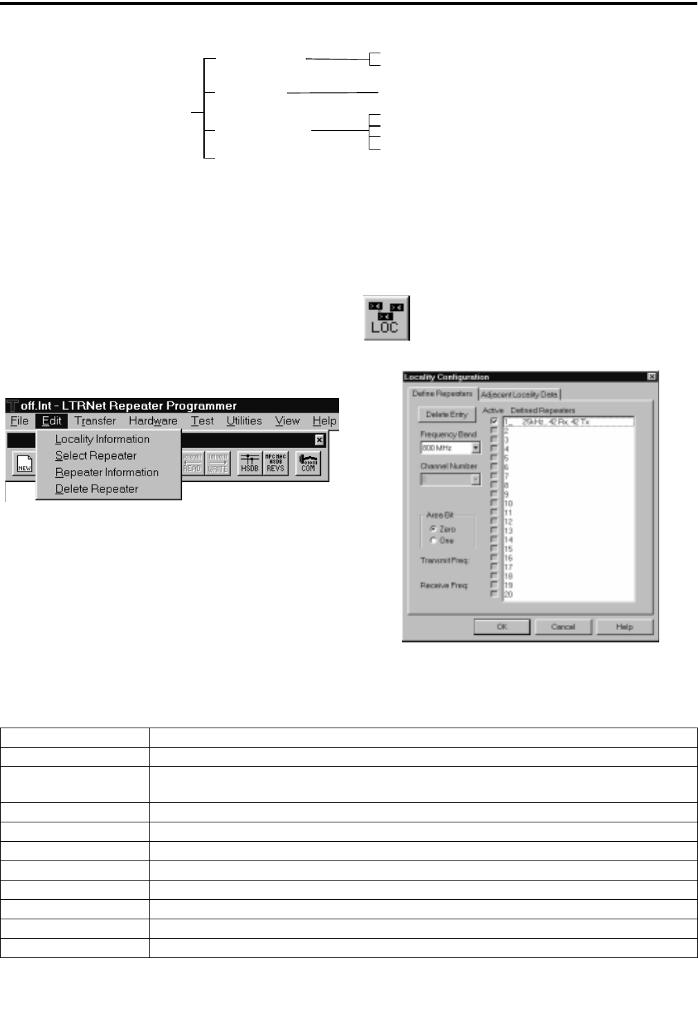
4.3.1 LOCALITY INFORMATION
This menu selection has an equivalent icon in
the toolbar. This menu selection or icon
brings up the Locality information screens to
Define Repeaters and Adjacent Localities.
Figure 4-6 LOCALITY CONFIGURAITON
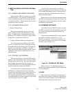
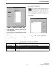
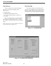
4.3 EDIT
This menu is used to create new files and set or
change the repeater operating parameters. The file-
name for the Locality and relevant data is shown in the
Title Bar and Status Bar (see Section 4.8.1).
Figure 4-5 EDIT MENU
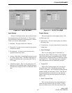
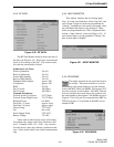
Table 4-1 DEFINE REPEATERS PARAMETERS
Delete Entry Removes the selected Defined Repeater from the list.
Frequency Band Selects the Locality frequency band, 800 MHz, 800 MHz with offset, (or 900 MHz).
Channel Number Select a repeater number in the Defined Repeater pane and assign the channel number (1-920).
See Appendix A for an 800 MHz Frequency Chart.
Area Bit If the coverage area includes more than one Switch the area bit is used, this is normally 0.
Transmit Frequency This is displayed for reference and is determined when the Channel Number is selected.
Receive Frequency This is displayed for reference and is determined when the Channel Number is selected.
Active Click on this box to activate the selected Defined Repeater.
Defined Repeaters Click on a repeater number, then select the channel number and the data is displayed.
OK Saves the current selections shown and closes the window.
Cancel Disregards all changes and closes the window.
Help Displays the Help screen for the parameters in this window.