


SERVICING
8-3
March 1999
Part No. 001-2009-600
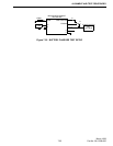
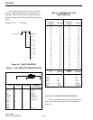
Measure the prescaler input frequency at fin, pin
11. Then measure the output frequency at TEST 2,
pin 13 and calculate the divide number. If the VCO is
not locked on frequency, the divide number should
still be correct. The measured frequencies may not be
exactly as calculated due to counter accuracy and res-
olution limitations.
NOTE: The counter should be connected to a high
stability reference oscillator.
Example: Channel 300, VCO locked on frequency
845.550 MHz (pin 11) ÷ 13.200 (pin 13) = 64.0568
8.2.5 CALCULATING "N " AND "A " COUNTER
DIVIDE NUMBERS
"N" Counter
N Counter Divide Number =
Integer (VCO Freq. (MHz) ÷ 0.8)
Example: Channel 200 (receive)
VCO freq = 898.500 - 52.95 = 845.550 MHz
N Cntr Div No = 845.550 ÷ 0.8 = 1056.9375
Integer (whole no.) of 1056.9375 = 1056
Example: Channel 200 (transmit)
N Cntr Div No = 937.500 ÷ 0.8 = 1171.8750
Integer (whole no.) of 1171.8750 = 1171
"A" Counter
A Counter Divide Number =
(VCO freq (MHz) ÷ .0125) - (N Cntr Div No x 64)
Example: Channel 200 (receive)
A Cntr Div No = (845.550 ÷ .0125) - (1056 x 64)
= 67,644 - 67,584
= 60
Example: Channel 200 (transmit)
A Cntr Div No = (937.500 ÷ .0125) - (1171 x 64)
= 75,000 - 74,944
= 56
8.3 RECEIVER SERVICING
To isolate a receiver problem to a defective sec-
tion, start by checking the DC voltages shown in Sec-
tion 6.6.6 and on the schematic diagram (Section 10).
If that does not indicate the problem, perform the per-
formance tests in Section 7.2 to isolate the problem. If
the synthesizer is out of lock, the receiver is also non-
functional because the first injection and IF signals
will be incorrect.
8.4 TRANSMITTER SERVICING
To isolate a transmitter problem to a defective
section, start by checking the DC voltages shown in
Sections 6.6.4 and 6.6.6 and on the schematic diagram
(Section 10). If that does not indicate the problem,
perform the Performance Tests in Section 7.3, 7.4 and
7.5 to isolate the problem. If the synthesizer is out of
lock, the Exciter is also nonfunctional because the
software will not allow the repeater to transmit.
8.5 POWER SUPPLY SERVICING
The power supply is a switch mode type with
very high voltages. It is highly recommended that the
power supply be returned to the factory for servicing
(see Section 1.8). A parts list, schematic and compo-