


ALIGNMENT AND TEST PROCEDURES
7-5
March 1999
Part No. 001-2009-600
11.Use the "Turn on carrier" button to unkey the
Exciter.
12.Repeat Steps 1-7. Very little adjustment of R446
should be needed.
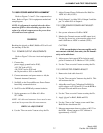
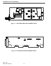
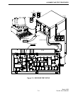
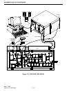
7.4 75W POWER AMPLIFIER ALIGNMENT
7.4.1 INTRODUCTION
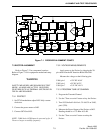
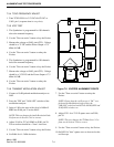
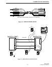
Refer to Figures 7-3 and 7-5 for component loca-
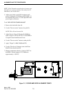
tions. Refer to Figure 7-11 for equipment needed and
setup diagram.
Select "PA" from the "TEST" menu in the
Repeater Programming Software.
IMPORTANT NOTE
No field alignment is required. Adjustments in
Sections 7.4.2 and 7.4.4 are part of a new unit pro-
duction test procedure. They should only be per-
formed as required on "out-of-warranty" and
"field-repaired" units. Broken seals on R76, R663
or R680 will void the warranty! Full power control
range of 25-75W is controlled by the repeater con-
figuration parameters under the Edit-Setup
Parameters menu selection.
The adjustments in Section 7.4.2 provide for
proper matching for the output of Q501 and set a pro-
tective limit on the drive to the final transistors. This
limit is approached only under certain unusual operat-
ing or repair conditions. However, improper adjust-
ment may impair normal operation of the PA, espe-
cially at temperature extremes.
If Q501 or U501 are replaced, only Section 7.4.2
adjustments should be performed. No other adjust-
ments are necessary in this case. Replacement of RF
components surrounding Q501 and U501 does not jus-
tify performance of Section 7.4.2 adjustments.
Replacement of active components within the power
control circuitry of the RF Interface Board would
require Section 7.4.2 adjustments.
Section 7.4.2 adjustments are necessary only if
repairs are made and such repairs are likely to affect
the sensitivity/calibration of the forward or reverse
power detectors (e.g. replacement of detector diodes
CR651/CR652 or of the entire forward/reverse power
detector assembly). Replacement of components
within the power control circuitry of the RF Interface
Board are unlikely to affect the calibration of the
power control.
NOTE: Replacement of Q501, Q502, Q503 or U501
does not
require the adjustments in Section 7.4.2.
7.4.2 FORWARD POWER OUTPUT CALIBRA-
TION
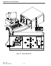
1. Connect the:
power supply ground lead to P105,
+15V DC lead to P103,
+26.5V DC lead to P101 and
the 36-pin cable to J101 on the RFIB.
2. Connect attenuator and power meter to A8.
3. Set R663 fully counterclockwise.
4. Set R76 on the RFIB fully counterclockwise.
5. Set the signal generator to +16 dBm ±0.1 dB at
937.5 MHz.
NOTE: All cable and attenuator losses must be mea-
sured and incorporated into this measurement.
CRITICAL ADJUSTMENTS
6. Use the "Turn on carrier" button to key the PA.
7. Adjust R663 for 85W ±2W (±0.1 dB).
8. Verify that Output 1 is within 20% of
Output 2.
9. Use the "Turn on carrier" button to unkey the PA.
7.4.3 PRE-DRIVER POWER LIMIT ADJUST-
MENT
1. Set a power reference of 0 dB at 85W.
2. Monitor the Transmit current and RF output level.
Use the Up Arrow key to increase the power level
until 0.6 dB above 85W (97W) is reached or peak
PA output.