


CIRCUIT DESCRIPTION
6-35
March 1999
Part No. 001-2009-600
6.11.3 HIGH SPEED DATA BUS MICROPRO-
CESSOR
The HSDB processor (U13) on the MPC pro-
vides the interface with the HSDB. It monitors data
on this bus and also transmits data on to this bus when
necessary. Information on this bus indicates which
repeaters are in use and also which mobiles are using
the system. This information is used by the repeater to
encode data messages to the mobiles that are monitor-
ing that channel. These messages also include infor-
mation on which repeater is free and current system
priority.
Microprocessor U13 is an 8052 that uses external
EPROM (Erasable Programmable Read Only Mem-
ory) U14, an 8-bit device that stores the program. The
microprocessor uses 2k x 8 EPROM and 64k x 8
RAM. The RAM (Random Access Memory) is used
for temporary data storage. The HSDB processor is
configured by the Main Processor.
The internal data bus of the microprocessor has
four input/output ports. These ports have eight lines
each, giving a total of 32 input/output lines that are
designated P0, P1, P2, P3. P0 is used as a data bus.
Ports P1 and P2 are always used as general purpose
inputs/outputs. P3 is used for specialized functions,
i.e. a serial port (RxD/TxD) and interrupt (INT).
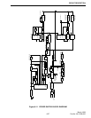
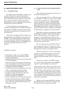
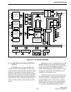
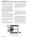
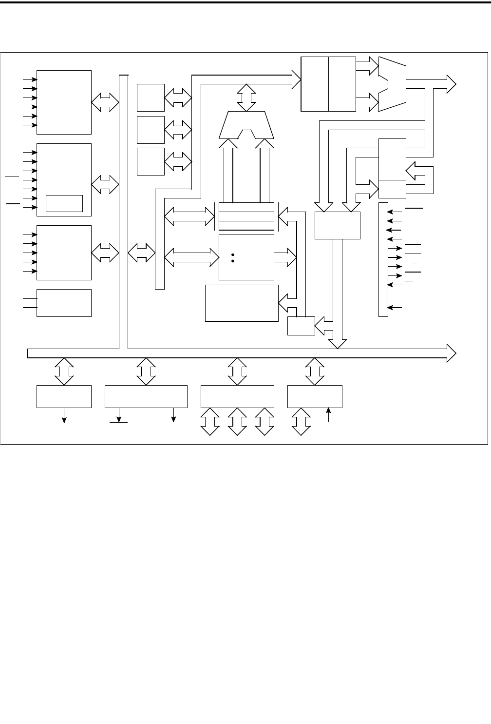
Figure 6-15 U27 BLOCK DIAGRAM
PROGRAMMABLE
DMA
CONTROLLER
SERIAL
COMMUNICATION
INTERFACE
GENERATOR
BAUD RATE
PROGRAMMABLE
INTERRUPT
CONTROLLER
CLOCK
TIME BASE CONTROLLER
PORT
PORT WITH
COMPARATOR
P2-0
P2-1
P2-2
P2-3
P2-4
P2-5
TxD0
RxD0
P1-6
CTS0
TxD1
RxD1
CTS1
P1-0
P1-1
P1-2
P1-3
P1-4
X1
X2
16-BIT TIMER
P1-5 REFRQ P0-7
P0 P1 P2 PT0-PT7
V
TH
LC
etc.
PSW
PC
ALU
TA
TB
TC
INT RAM
256 BYTES
GR
MACRO
SERVICE
CHANNEL
INSTRUCTION DECODER
MICRO SEQUENCER
MICRO ROM
QUEUE
INT ROM
P1-4
EA
IOSTB
R/W
MREQ
MSTB
P1-7
P2-7
P2-6
RESET
BUS CONTROL LOGIC
D7-D0
INC
PFP
STAGING
LATCH
STAGING
LATCH
ADM A19-A0
16K BYTES