


CIRCUIT DESCRIPTION
6-4
March 1999
Part No. 001-2009-600
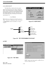
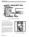
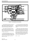
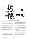
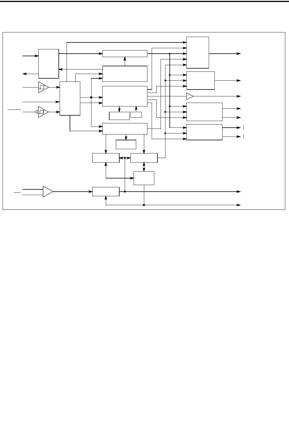
Figure 6-3 SYNTHESIZER BLOCK DIAGRAM
(OPEN-DRAIN OUTPUT)
15
OUTPUT B
DATA OUT
24 BITS
A REGISTER
INPUT AMP
PRESCALER
64/65
in
f
in
f
10
11
LOGIC
MODULUS
CONTROL
N COUNTER
12-STAGE
A COUNTER
6-STAGE
CONTROL
INTERNAL
POR
LOGIC
STANDBY
8 BITS
C REGISTER
ENABLE
17
19
DATA IN
CLOCK
18
LOGIC
CONTROL
AND
REGISTER
SHIFT
16 BITS
R REGISTER
DOUBLE-BUFFERED
13-STAGE R COUNTER
DIVIDER
4-STAGE
OSC OR
out
REF
20
in
REF
1
OR (UP)
OV (DOWN)
16
OUTPUT A
LOGIC
SELECT
PORT
V
f
R
f
V
R
2LOCK DETECT
AND CONTROL
LD
f
f
V
R
f
f
PHASE/FREQUENCY
DETECTOR B
AND CONTROL
PHASE/FREQUENCY
AND CONTROL
DETECTOR A
V
R
f
f
3
4
8
6
Rx
PDout
TEST 2
TEST 1
13
9
The programming of the counters in U205 is per-
formed by circuitry in the Main Processor Card
(MPC), buffered and latched through the Interface
Alarm Card (IAC) and fed in to the synthesizer on
J201, pin 20 to Data input port U205, pin 19.
Data is loaded into U205 serially on the Data
input port U205, pin 19 when U205, pin 17 is low.
Data is clocked into the shift registers a bit at a time
by a low to high transition on the Clock input port
U205, pin 18. The Clock pulses come from the MPC
via the IAC to J201, pin 19.
The counter divide numbers are chosen so the
TCXO-derived input to the phase detector (f
V) is the
same frequency as the OCXO-derived input (f
R). The
f
R input is produced by dividing the 1.25 MHz OCXO
frequency by 125. This produces a reference fre-
quency (f
R) of 10 kHz.
The fV input is produced by dividing the TCXO
frequency using the prescaler and N counter in U205.
The prescaler divides by 64 or 65. The divide number
of the prescaler is controlled by the N and A counters
in U205.
Both the N and A counters begin counting down
from their programmed number. When the A counter
reaches zero, it halts until the N counter reaches zero.
Both counters then reset and the cycle repeats. The A
counter is always programmed with a smaller number
than the N counter. While the A counter is counting
down, the prescaler divides by 65. Then when the A
counter is halted, the prescaler divides by 64. As an
example: To produce the frequency of 10 kHz, the N
and A counters are programmed as follows:
N = 27 A = 22