


CIRCUIT DESCRIPTION
6-39
March 1999
Part No. 001-2009-600
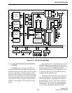
data, and noise. The audio processing circuit provides
filtering and amplification of the audio signal before it
is routed to the outputs on the MAC card.
A low-pass filter consisting of U121A/B attenu-
ates frequencies above 3 kHz. This removes high-fre-
quency noise from the audio signal. From the filter
the signal is fed to amplifier U122A to increase the
level before the high-pass filter to preserve adequate
hum and noise ratio.
From the audio amplifier the signal is fed to a
high-pass filter consisting of U122B/C/D. This filter
attenuates frequencies below 300 Hz which removes
data present in the wide band audio signal. These fil-
ters are configured to act like large inductors. The sig-
nal is then fed to U163A which provides 6 dB per
octave de-emphasis.
Audio gates U113B/C/D permit noise squelch cir-
cuit, control logic, and audio switch to control gating
of the audio signal. The control signal from the noise
squelch circuit is applied to U113B through U113D.
When a carrier is detected, this input is high and
U113B passes the signal. Programming determines
the gating of audio. When audio is passed by U113B/
C and U114A, the audio can be routed through other
gates to various outputs (see Section 6.12.6).
6.12.4 RECEIVE SQUELCH CIRCUITRY
The receive wide band audio includes audio, data
and noise. The squelch circuit detects this noise to
determine receive signal strength. When no carrier or
a weak carrier is received, there is a large amount of
noise present. Conversely, when a strong carrier is
present, there is very little noise present.
U135A is a high-pass filter which attenuates fre-
quencies below approximately 30 kHz so that only
high-frequency noise is passed. This noise is ampli-
fied by U135B and U123A. A level control adjusts
the gain of amplifier U135B. The gain of U123A is
partially set by a thermistor to compensate for circuit
gain and noise level changes caused by temperature
variations.
The amplified noise is then applied to a bridge
rectifier. The difference between bridge rectifier out-
puts is applied to the inputs of U123B. The output of
U123B is positive-going pulses. These pulses are
applied to U123C which is a Schmitt trigger. When
the input signal rises above the reference, the output
goes low and causes the reference voltage to decrease
slightly adding hysteresis to the triggering level. This
hysteresis prevents intermittent squelching when the
receive signal strength is near the threshold level.
The output of U123C is applied to U123D and
Logic Squelch to Audio/Data Gate U159B and audio/
data processor U111. Gate U159B routes the squelch
output to the Audio/Data Test Point J100. U123D
functions as a timing buffer. The output of U123D is
applied to Receive Squelch Active Gate U113D.
When this gate is closed, the squelch circuit controls
Normal Receive Gate U113B to block receive audio if
no signal is present.
6.12.5 RECEIVE DATA CIRCUITRY
The receive wide band audio signal is the unfil-
tered output of discriminator U202 in the Receiver.
Therefore, this signal contains audio, LTR data, and
noise. A low-pass filter formed by U124A/B attenu-
ates frequencies above 150 Hz by 24 dB per octave so
that only the data frequencies are passed. From the fil-
ter the signal is fed to amplifier U125A. The gain of
U125A is adjusted by a level control. The output of
U125A can be routed through Data To Audio/Date
Gate U159C and the Audio/Data Test Point J100.
DC restoration circuit converts the data signal
from AC floating near ground to a digital signal at lev-
els of 0 and 4.5V. U125B/C provide the reference
voltage on the inverting input of comparator U125D.
Positive peak detector U125B handles the positive-
going peaks of the data signal. Negative peak detector
U125C handles the negative-going peaks of the data
signal.
The voltage on non-inverting input to U125D is
midway between the positive- and negative-going
peaks. The data input is on the non-inverting input of
U125D. When the data signal rises above the refer-
ence voltage, the output goes high. Conversely, when
the input voltage drops below the reference voltage,
the output goes low. The receive data is then passed to
audio/data processor U111.