


CIRCUIT DESCRIPTION
6-30
March 1999
Part No. 001-2009-600
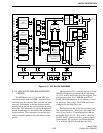
The majority of the voltage and current limits are
set with fixed value components in the power supply.
However, the +26.5V, +15V and +5.2V supplies are
adjustable. When certain components are replaced,
the voltages must be adjusted. The voltages should be
set at light load (i.e. repeater in the Receive mode).
1. The +26.5V supply can be adjusted with R174 when
any of the following components are replaced:
R173, R174, R175, U109, U108, U102, R143, R170
or R171.
2. The +15V supply can be adjusted with R216 when
any of the following components are replaced:
R215, R216, R217 or U112.
3. The +5.2V supply can be adjusted with R254 when
any of the following components are replaced:
R253, R254, R255 or U113.
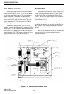
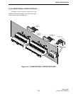
6.8 BATTERY BACK-UP MODULE
6.8.1 OPERATION
When a battery back-up module is installed in a
power supply it performs the function of running a
repeater in the absence of AC voltage. When AC is
present it can be used to charge a pair of lead-acid bat-
teries in series. The charger is a temperature compen-
sated constant voltage charger. The maximum output
current from the charger is 2.2A. The charger works
when AC is present and the repeater is enabled. The
charger switch on the battery back-up module must be
"On". The temperature compensation thermal sensor
is part of 023-2000-223 battery back-up module cable
assembly.
When AC is low or not applied to the 023-2000-
800 power supply the battery input takes over if the
voltage is within range. The input voltage to the bat-
tery back-up module acts as the 26.5V supply and the
other voltages in the power supply also are present,
+15, +5.2 and -5V. When AC is restored, the battery
back-up module disengages automatically. The
change over from battery to AC or AC to battery may
cause the repeater to reset, depending on battery con-
dition and load status.
NOTE: When using a generator, the DC voltage must
be between 23-28.5V (26.5V DC is recommended) and
ripple voltage less than 1% or approximately
0.25V P-P.
6.8.2 CHARGER
The charger charges the batteries when the
repeater is on and switch S101 is "on". A tap off of
the main transformer of the power supply through wire
W104 and a +26.5V line via wire W102 are what sup-
ply the charger with the necessary voltage to charge
the batteries. The tap off of the transformer is biased
by the +26.5V and then filtered through L101, C105
and C119. Since the tap from the power supply is not
a regulated voltage, bleeder resistors R136/R137 dissi-
pate some power when the batteries are fully charged.
No load situation, the peak voltage of the tap is
approximately 63V, is not impressed across the 50V
capacitors C105/C119. During a battery charging con-
dition the line voltage to the charger on U107, pin 2
should be about 35V.
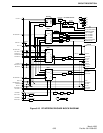
While charging batteries, if the charge voltage is
varied with respect to the temperature of the batteries,
the lifetime of the batteries is increased dramatically.
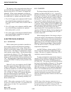
Figure 6-12 shows the algorithm used in float charge
applications for two 12V lead-acid batteries in series.
Figure 6-12 shows that the charge voltage should be
27.3V DC ±0.15V at 25°C (77°F) with -55 mV/°C
temperature compensation.
An LM317M linear voltage regulator (U107) is
used to create the temperature compensated charge
voltage. This device is capable of delivering 2.2A of
continuous current to the batteries.
To create a temperature compensated voltage an
op amp (U104) is used as a voltage gain device from a
temperature probe attached to the batteries (part of
023-2000-223). This op amp with R148/R149 defines
the slope for the algorithm of Figure 6-12. The output
of the temperature compensation is attached to the
adjust pin of U107. R138-R140 allow the output volt-
age to be set properly at a given ambient temperature.
F101 is a 4A resettable fuse used to prevent thermal
run away in the event of U107 failure. If the output
current to the batteries exceeds 4A this fuse opens.
Once the current drops below 100 mA, the fuse closes
automatically.
NOTE: If any of the charging components are re-
placed, R140 needs to be adjusted to set the output (bat-
tery back-up battery terminals) voltage to 27.3V
±0.15V when temperature sensor is at 22°C (71.6°F).