


ALIGNMENT AND TEST PROCEDURES
7-21
March 1999
Part No. 001-2009-600
2. Verify that the repeater is programmed for "Stand
Alone" mode in Setup Parameters-F4 (see Section
4.3.3).
3. The repeater is now in Normal Operation mode.
Verify by the MPC front panel indicators that no
HSDB alarms have occurred (Alarm Number 10)
see Table 1-2.
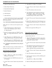
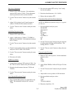
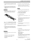
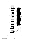
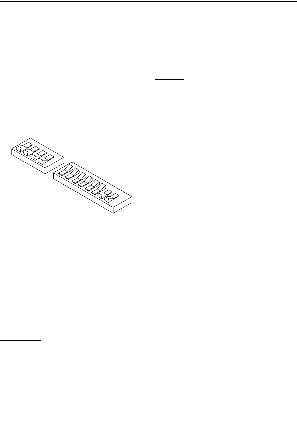
Old HSDB Test
1. Switch settings on the MPC for single-ended 5V
(old style) operation are shown in Figure 7-19.
S002 Sections 1-8 Off. S003 all sections On.
Figure 7-19 OLD HSDB SWITCH SETTINGS
2. Verify that the repeater is programmed for "Stand
Alone" mode in Setup Parameters-F4 (see Section
4.3.3).
3. The repeater is now in Normal Operation mode.
Verify by the MPC front panel indicators that no
HSDB alarms have occurred (Alarm Number 10)
see Table 1-2.
Handshake Test
1. Program an LTR, portable or mobile, for the follow-
ing parameters.
Home Repeater - Same as repeater number.
Home Channel - Same as repeater channel.
Area - Same as repeater’s area bit.
Encode ID - 1
Decode ID - 1
2. The repeater is now in Normal Operation mode.
3. Key the radio several times on the programmed Sys-
tem/Group. Access should occur every time.
(Proper Tx/Rx antenna connections are assumed.)
Alarm Test
1. The repeater is now in Normal Operation mode.
2. Verify by the MPC front panel indicators that no
alarms have occurred (see Table 1-2).
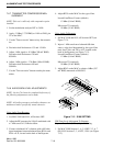
7.7 SWITCH (RNT) INTERFACE
7.7.1 REPEATER SETUP
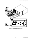
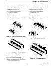
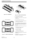
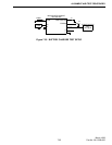
1. Connect the repeater as shown in Figures 7-7, 7-20
and 7-21.
2. Adjust the repeater for the type of link used for com-
munication back to the CIM in the Switch. The
types of links used are:
Leased Lines (LL)
Direct Connection (DC)
Microwave (MW)
T1 Interfaces (T1)
3. Program the repeater for the specified parameters
using the Programmer.
NOTE: Assume all audio generators and voltmeters to
be unbalanced unless stated otherwise.
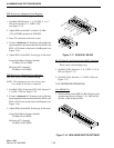
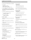
7.7.2 CIM SETUP
1. Adjust the CIM for the type of link used for commu-
nication back to the repeater. The types of links
used are:
Leased Lines (LL)
Direct Connection (DC)
Microwave (MW)
T1 Interfaces (T1)
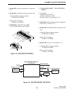
Refer to the LTR-Net Switch, Setup and Alignment
manual, PN 001-3239-001, for more information on
the CIM alignment (see Figure 7-31).
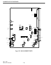
2. Connect the link lines to the Switch and its associ-
ated CIM (see Figure 7-21).
O
N
O
N
S3
S2
2
1
8
7
6
5
4
3
2
1
4
3