


ALIGNMENT AND TEST PROCEDURES
7-24
March 1999
Part No. 001-2009-600
7.7.6 FSK LINK - FSK DATA LEVEL TO SWITCH
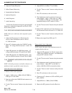
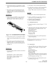
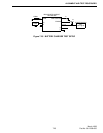
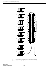
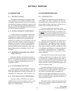
1. On the MAC,
set S100 all Sections OFF
set S101, sections 2, 3, 4 OFF
set S101, section 1 ON (see Figure 7-23).
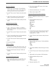
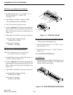
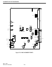
2. Connect a balanced AC voltmeter with 600 ohm
input impedance between balanced lines RXA+ and
RXA- of J2 located on the back of the Repeater (see
Figure 7-20).
3. On the MAC, adjust R240 for the type of line used.
Leased Line/Direct Connect (default)
-22 dBm (62 mV RMS)
Microwave/T1 (optional)
-38 dBm (10 mV RMS)
7.8 VISUAL CHECK
1. Make sure the heat sunk parts are not shorted to the
heat-sink.
2. Verify all electrolytic capacitors are installed cor-
rectly.
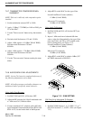
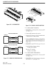
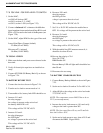
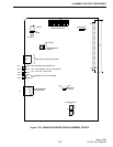
3. Connect 023-2000-830 Battery Back-Up as shown
in Figure 7-24.
7.9 BATTERY REVERT TEST
1. Connect the circuit as shown in Figure 7-24.
2. Turn the active load to current mode at 1A.
3. Turn enable to On, battery fault LED should be on.
4. Increase Vs1 until:
the relay engages
the voltage is present on the active load
the battery fault LED is off.
This voltage will be 22V DC ±0.5V.
5. Increase Vs1 until:
the relay disengages
the LED lights
no voltage is present at the active load.
This voltage will be 31V DC ±0.5V.
6. Decrease VS1 until:
the relay engages
the LED goes out
voltage is present at the active load.
This voltage will be 28V DC ±0.5V.
7. Set Vs1 to 26.5V DC and turn the enable line to
OFF. No voltage will be present at the active load.
8. Decrease Vs1 until:
the relay disengages
the LED lights
no voltage is present at the active load.
This voltage will be 19V DC ±0.5V.
9. With the enable line OFF measure current Is, it
should be less than 20 mA.
10.Reverse the polarity of Vs1
Set to 26.5V DC
BBM Enable ON
Reverse Battery LED will light and Is should be less
than 50 mA.
11.Disconnect the test setup.
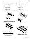
7.10 BATTERY CHARGER SECTION
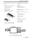
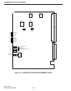
1. Connect Battery Backup Module as shown in Figure
7-25.
2. Set the active load to 0A and set Vs2 to 40V at 3A.
3. Adjust R140 so the voltage at the active load reads
27.55V DC ±0.1V.
NOTE: The temperature sensor LM335 has to be at
22°C (room temperature).
4. Increase the active load current to 1.8A and verify
voltage at the load is greater than 26V.
NOTE: The fan control line will stay at 0V until the
heat sink is above 50°C.
5. Set the active load current to zero, shut off Vs2 and
disconnect the BBM. Glyptol R140.