


Overview
How to Program a Strata DK System
1-10 Strata DK Programming 5/99
How to Program a Strata DK System
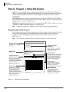
Fill out the record sheets that are provided, then enter this data using a 20-button LCD digital
(DKT) or electronic (EKT) telephone. Strata DK enables you to enter data from an on-site or off-
site PC with Toshiba DKAdmin software. Toshiba highly recommends this easier method of
programming.
DK14/DK40i: the programming telephone must be any 20-button LCD DKT (or EKT, DK40i
only). The DKT must be connected to a Base KSU, PDKU, RDSU, QCDU, or KCDU digital port.
An EKT must be connected to a PEKU port.
DK424: the programming telephone must be a 20-button LCD DKT or EKT connected to circuit 6
of a PDKU or PEKU installed in cabinet slot 11 and/or slot 12.
Note Telephones connected to an RDSU or PESU cannot be used to program DK424.
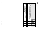
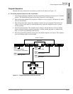
Programming Section Layout
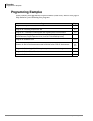
Each programming section within a chapter begins with the program’s number and title, followed
by processor and program type, initialized default, program sequence, then record sheets. A
program overview and additional program information are given after the record sheets
(see Figure 1-1).
Note Some common program sections also include examples for your convenience.
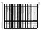
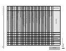
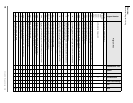
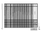
Program 30 Overview
Program 30 Station Class of Service
System Programs
Program 30 enables or disables features for individual telephones at the station level. The following text
describes Program 30 LEDs.
Privacy Override, LED 19
With Privacy Override enabled (LED 19 ON), a station can override calls and listen to a CO line
conversation by pressing a common CO line button (not a [DN] button). You can set a warning tone for
Privacy Override (see Program 10-2).
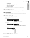
SELECT = Station Logical Port Number(s) Buttons/LEDs
Light LEDs for the port specified in the
last step. All LEDs marked with an “X”
in the table below should be lit.
2174
Feature LED
20
19
18
17
16
15
14
13
12
11
10
09
08
07
06
05
Port
Processor Type: DK14/DK40/DK424
Program Type: System
Initialized Default: LEDs 01, 05 and 07 for all ports
Program 30
Station Class of Service
Program 30 Station Class of Service
System Programs
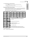
Number/Title
Program Sequence
Record Sheet
Program Overview
Additional Program
Information
Processor Type
Program Type
Gives the type of processor that is
compatible with the given program.
Be sure to read this information
before attempting to use a program
with your system application.
Type of function the program
performs. Can be: Initialization,
Test System, Station, Toll
Restriction or Least Cost Routing.
Default configuration set by
Program 91-9 “System
Initialization” when the system is
first installed or re-initialized.
Additional details on the program
features that were given on the
system record sheet.
Keystrokes for entering data
from system record sheets
follow a pattern, consisting of a
five-step process described and
illustrated in “Program
Sequence” on Page 1-13.
Provides a list of available
features. The sheet is used to
record the assignment of
features or the operation of each
program. Each sheet provides
space to record data. This data
will be referred to when
programming the system.
Brief description of program
function(s).
Initialized Default
Figure 1-1 System Record Sheet Sample