


System & Station
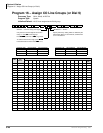
Program 20 – Computer and Data Interface Unit Configuration
3-56 Strata DK Programming 5/99
● If a PC is connected to the RPCI or PDIU, set the communication mode escape sequences in
the PC communication software “Modem Initialization” character sequence. This ensures the
escape sequence is restored in case the RPCI Telephone or PDIU is unplugged temporarily.
● RPCI and PDIU-DS units that mostly do data switching, can be connected to ports associated
with PDKU1 circuits 1~7 only. All PDKU2 circuits, 1~8, support RPCIs and PDIUs. RDSU
digital circuits 5~8 support RPCI and PDIUs.
● Each PDIU-DS requires a separate digital port.
● If a PDIU-DS (Stand-alone Data Interface Unit) is connected to a modem, refer to Modem
Setup Recommendations in the PC/Data Communication section of Chapter 10 – Peripheral
Installation of the Installation and Maintenance Manual.
● See Chapter 10 – Peripheral Installation for additional hardware information and Chapter 2 –
DK40i Configuration and Chapter 4 – DK424 Configuration to identify which slots can
support RPCIs and DIUs.
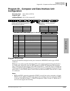
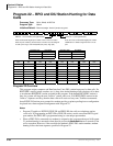
Typical LED Settings for Program 20
RCPI-DI/PDIU-DI Connected to a terminal or personal computer—LEDs 01, 02, 05, and 17 ON;
all other LEDs OFF.
PDIU-DS Connected to a Printer: LEDs 01, 04, and 17 ON; all other LEDs OFF.
PDIU-DS Connected to a Modem: LEDs 01, 02, 03, 04, and 17 ON; all other LEDs OFF.
LEDs 17~20: Data Security Groups
Data security groups can be set to block data calls between RPCI/DIUs. RPCI/DIUs can only
make data calls to RPCI/DIUs in the same security group. LEDs 17~20 assign the RPCI/DIU to
the appropriate security group: light LED 17 for Group 1; LED 18, for Group 3; LED 19, for
Group 2; and LED 20, for Group 4. If an RPCI-DI is used in the Application Program Interface
(TAPI) mode only, and not the Data Switching mode, this option is not applicable.
LEDs 12~16
Not used at this time.
LED 11: RPCI-DI DNIS to PC Option
DNIS Number or NAME tag information that is sent to a telephone can be sent, or blocked, from
the telephone’s RPCI-DI, RS-232 output. If DNIS information should be sent from the
Telephone’s RPCI-DI to the Personal Computer to which it is connected, turn LED 11 ON; if this
information should not be sent to the PC, turn LED 11 OFF.
LED 10: RPCI-DI Caller ID and ANI to PC Option
Caller ID and ANI information that is sent to a telephone can be sent, or blocked, from the
telephone’s RPCI-DI, RS-232 output. If Caller ID and ANI information should be sent from the
RPCI-DI to the Personal Computer to which it is connected, turn LED 10 ON; if this information
should not be sent to the PC, turn LED 10 OFF. This option does not apply to PDIUs because they
can not send ANI, Caller ID, or DNIS numbers.
LEDs 07~09
Not used at this time.