


System & Station
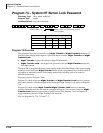
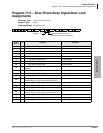
Program 77-1 – Peripheral Options (Door Phones)
3-160 Strata DK Programming 5/99
Program 77-1 Overview
This program performs the following functions:
♦ Programs door lock relays
♦ Assigns door phones/lock control units
♦ Enables RMDS/IMDU built-in maintenance modems
♦ Sets RMDS communications standard type
♦ Enables DKAdmin Communications Protocol
♦ Enables/disables door phone ring tone to external paging when system is in Night mode
♦ Assigns a relay to operate with door lock function or external page for mute control
♦ Assigns a relay to operate in one of two Night Transfer modes
♦ Assigns a relay to operate in one of two applications
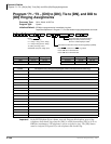
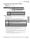
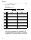
LED 20: Door Lock Time
The Door Lock Relay contact may be programmed to operate for either three or six seconds
(applies to PIOU, PIOUS, PEPU, DDCB, and HDCB door lock controls).
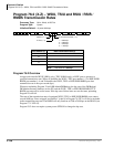
LEDs 16~19: Port Number/Door Phone/Lock Control Units
Door phone/lock existence is defined by this program. The door lock option is set via Program
77-2.
♦ DK424: Door phone/lock controllers (DDCBs and/or HDCBs) can only exist at Ports 004,
012, 020 and 028, and can only be installed on Circuit 5 of a PDKU, RDSU, PEKU and/or
PESU. PDKUs and RDSUs support DDCBs, but not HDCBs. PEKUs and PESUs can support
HDCBs, but not DDCBs. After assignment of a DDCB or HDCB, door phone numbers
(#151~#159, #161~#163) effectively replace the station number assignment in Program 04.
Up to four DDCBs/HDCBs can be installed in a system with RCTUB, RCTUBA/BB and C/D,
only 3 are allowed with RCTUA. They must be assigned a PDKU, RDSU, PEKU or PESU
port number to operate (DDCB to PDKU or RDSU, and HDCB to PEKU or PESU). (See
Program 79 and 79 for door phone ringing assignments)
Station PCBs that are connected to HDCB/DDCB door phones control boxes must be installed
in lower slot numbers than Tie, DID, or Attendant Console PCBs.
♦ DK40i and DK14: See port information on record sheet.
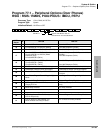
LED 15: RMDS Protocol
This program sets the RMDS communications standard type to CCITT/V.22bis (2400bps) or Bell
212A (1200bps). The standard set in this program must match the standard of the modem that will
be used to communicate with the Strata DK RMDS.
♦ If the RMDS modem standard should be 2400bps/CCITT/ V.22bis, turn LED 15 on; if the
RMDS standard is a 1200 bps/Bell 212A, turn LED 15 off. Most Hayes compatible modems
will function with either standard; check with the modem manufacturer’s documentation to
verify which protocol should be used. When the system is initialized the Bell 212A (1200 bps)
standard is set (LED 15 off).
♦ IMDU can be 1200 bps or 300 bps as set by SW2 on the PIOU or PIOUS PCB; RMDS can be
1200 bps or 2400 bps as set in Program 76-2 and Program 77-1 LED 15.