


System & Station
Program 31 – Station Class of Service
3-80 Strata DK Programming 5/99
Program 31 – Station Class of Service
Processor Type:
DK14, DK40i, All RCTUs
Program Type:
Station
Initialized Default:
LED 10 ON for Ports 000~119
;
LED 11~13 ON for all ports.
Program 31 Overview
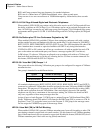
Program 31 sets most voice mail or External Auto Attendant port assignments. Each standard
telephone port (QSTU2, RSTU2, RSTU, PSTU, PESU, RDSU, KSTU2, QSTU2) connected to a
Toshiba Stratagy, Stratagy DK or VP voice mail system should have LEDs 04, 15, 16, 17, 18, 19,
and 20, and one of the following: 05, 06, 07, or 08 turned ON. These LED’s should be ON for VM
ports only, not for telephone ports.
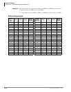
Processor Type Port Range Processor Type Port Range
DK14 000~009 RCTUBA/BB 000~079
DK40i 000~027 RCTUC/D 000~239
RCTUA 000~031 RCTUE/F 000~335
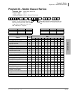
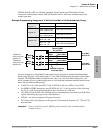
Feature LED
Port
Toshiba Stratagy/VP (B + Station No.) 20
Toshiba Stratagy/VP (B No Station) 19
Executive & Privacy Override Blocking 18
End/End Signal Rcv (VM) 17
Receive VM ID Code 16
Toshiba Stratagy/VP Integration (A/D) 15
Handset OCA 14
Handset OCA Warning Tone 13
Pooled Line Key - No Flash if No Ring 12
Busy Override Tone - Continuous 11
All Call Page Allowed - EKTs/DKTs 10
VM (No Conference) 09
VM Group 4 (does not apply to DK14) 08
VM Group 3 (does not apply to DK14) 07
VM Group 2 06
VM Group 1 05
VM to VM Call Blocking Called/Calling 04
OCA Enabled (To Receive) 03
Handsfree No Warning Tone 02
Handsfree Disabled 01
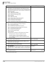
SELECT = Station Logical Port Number(s)
Enter the port numbers to which class of service
must be assigned.
Light LED Buttons for the port specified in the last
step. All LED Buttons marked with an “X” in the
table below should be lit.