


System & Station
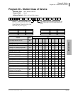
Program 30 – Station Class of Service
Strata DK Programming 5/99 3-77
System & Station
LED 04: Call Pickup Code Option
Determines the operation of pickup code
in Release 3.2 (and above) software. If LED 04 is
ON,
only picks up All Call Page and External Page (per Program 10-2, LED 15). If LED
04 is OFF,
picks up an internal call ringing on a telephone as a priority or it picks up All
Call Page or External Page if no internal calls are ringing. Prior to Release 3.2,
picked up
ringing calls as priority over All Call Page pickup calls.
LED 03: Microphone Button On at Start of Call
When enabled (LED 03 ON), the microphone and Mic button LED is turned ON at the start of an
on-hook speakerphone call. For this feature to work, you must enable the MIC button lock
operation (LED 02 ON).
When receiving internal DN calls, the flexible Microphone Cutoff (
0LFURSKQ&XWRII) button
(Program 39) can be used to prevent room monitoring and Handsfree Answerback.
LED 02: Mic Button - Locked/Momentary
The
0LF button turns electronic or digital telephone microphones ON/OFF:
With “Locked” (LED 02 ON), the
0LF button will be ON or OFF (depending on LED 03) when
you begin the call and you can alternately push it ON or OFF. This does not apply to Handset OCA
- which is
0LF push-to-talk only.
With “Momentary” (LED 02 OFF), the
0LF is always ON at the start of a speakerphone call/ You
must continuously press
0LF to disable the microphone when during a speakerphone call.
LED 01: Speakerphone
Enables (LED 01 ON) or disables (LED 01 OFF) speakerphone operation on any electronic or
digital telephone. If disabled, a speakerphone:
♦ Can be used as a handsfree electronic or digital telephone.
♦ Enables talk back with the receiver on-hook when receiving an internal call.
♦ Will not allow you to talk on a call that you place or a call that you answer by pressing a
ringing button with the handset on-hook.
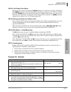
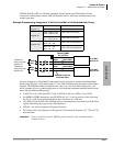
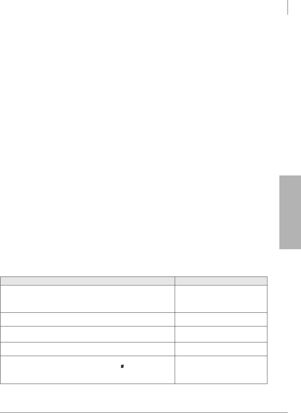
Program 30 - Example
Action (press buttons + LED buttons) LCD Response
1. Use an LCD programming phone per Minimum Hardware
Requirements on Page 1-14.
Make sure the programming button strip template is installed on the
programming telephone.
No. N-N
1
Jan 20 Sun 06:43
2.
Enter programming mode. (Do not press [DN] button.)
Program Mode
3. 6SNU6SHDNHU+ROG
Access Program 30.
Program = 30
Data Store
4. 6SNU6SHDNHU
Prepare the system for a station port selection.
30 Select =
5. Enter the port number where the station being defined is
connected. Use three digits, followed by a
button. A range of
ports may be entered at once by using the
button. (See Note
on system record sheet for port numbers.)
30 Select =