


58
SX-200 ICP MX Technician’s Handbook
Cabinet installation and programming
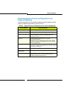
The following procedure applies to the installation of new peripheral
cabinets. Cabinets migrating from an existing SX-200 EL/ML installation
install in a different manner; see “Migrating an SX-200 EL/ML to an
SX-200 ICP” in the SX-200 ICP Technical Documentation for more
information
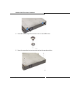
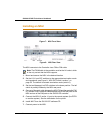
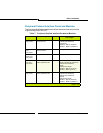
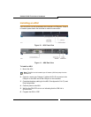
1. Install the peripheral cabinet (including Bay Power Supply, Bay Control
Card, interface cards and required Fiber or Copper Interface Module).
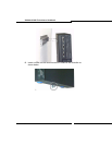
2. Complete the peripheral interface cabling.
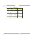
See Tip and Ring Assignment tables in Appendix C (page 365) for
cabling and cross connecting the peripheral cabinets.
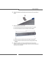
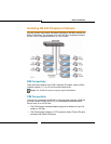
3. Connect one end of the fiber or copper cable to the interface module
in the control cabinet and the other end to the CIM or FIM connector in
the controller.
4. Power up the cabinet.
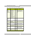
5. Enter CDE mode on the maintenance terminal.
6. In Form 04 (System Options/System Timers)
- Enable the required number of TDM Bays (Option 133)
- Make sure there are enough TDM devices available (Options 103).
7. In Form 53 (Bay Location Assignment)
- Assign a bay number to the CIM or FIM ports used to connect the
peripheral cabinets.
8. In Form 01 (System Configuration)
- Configure the cards (select node type as required).
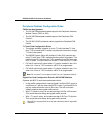
9. Complete the remaining CDE programming for the cards.
For detailed programming information, refer to the SX-200 ICP Technical
Documentation.