


55
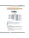
Basic Installation
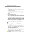
8. Program the NSU using CDE and IMAT; see page 112 for
programming instructions.
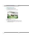
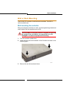
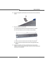
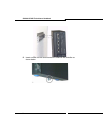
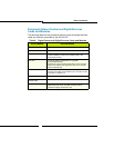
9. After programming the NSU, plug the T1 cable from the demarcation
point for the T1 provided by the Carrier to either L0 or L1 on the back
of the NSU. Each connector (L0 or L1) has LED indicators beside the
connector to indicate sync or not. For example:
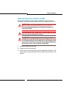
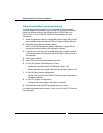
- Red LED indicates no sync (check connection or switch 6 is in
wrong position).
- Flashing green LED indicates synch but D-channel is not
synchronized (check programming (see table below) on IMATs to
ensure correct protocol).
- Solid green LED indicates that D-channels and B-channels are all
in sync and PRI trunks on NSU are ready to process calls.
.
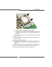
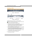
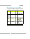
Figure 9: NSU DIP Switch Location
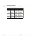
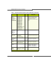
Table 5: Pinouts for T1 Line/Network Termination
Pin
Line
Termination Mode
Network
Termination Mode
1 Tx Ring Rx Ring
2 Tx Tip Rx Tip
3 Unused Unused
4 Rx Ring Tx Ring
5 Rx Tip Tx Tip
6 Unused Unused
7 Unused Unused
8 Unused Unused