


116
SX-200 ICP MX Technician’s Handbook
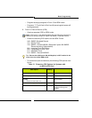
10. Form 43, T1 Link Assignment
- Assign the Link Descriptor to the PRI trunks (referencing the Bay
and Slot location).
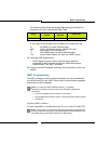
11. Form 44, Network Sync
- Enter the links according to their Bay/Slot/Circuit in the order that
you want them to be used as the network sync source. Typically,
CO’s are the first choice for a sync source. When using both PRI
and TI trunks, make the PRI trunk the clock source.
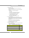
12. Form 22, Modified Digit Table
- DID Calling Party Number to the network interacts with the current
SX-200 ICP system networking functionality and ignores
programmed node-IDs in the NSU or PRI card. The Node ID
Information Element (“*8”) for Analog Networking, if programmed in
the Modified Digit Table, will be ignored by the NSU or PRI card. If
*6 is programmed in the digit modification table the DID calling
extension number is sent to the NSU or PRI card and can be sent
to the network as the calling party. The extension must belong to a
block of DID numbers purchased from the Network provider.
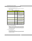
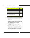
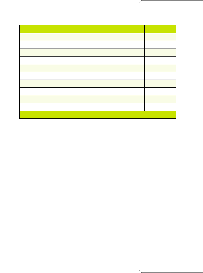
Slip rate – maintenance limit (0 – 9000) /24 hrs 255
Slip rate – service limit (0 – 9000) /24 hrs 7000
Slip rate – network sync limit (0 – 9000) /24 hrs 7
BER – maintenance limit ( 10**-n , n = (3,4,5,6 )) / hour 4
BER – service limit ( 10**-n , n = (3,4,5,6 )) / hour 3
Framing losses – maintenance limit (0 – 9000) /24 hrs 255
Framing losses – service limit (0 – 9000) /24 hrs 9000
RTS timer – service limit exceeded (1- 255 min) 30
RTS timer – net slip limit exceeded (1- 255 min) 30
RTS timer – after alarm (0 – 300 sec) 10
Table 17: T1 Link Descriptor Values for PRI trunks (continued)
Descriptor Value
(Page 2 of 2)