


USER’S MANUAL
Section 3: GUIDED TOUR of the HARDWARE 55
• Bridging≥10Kohmimpedance
Theinputsaredesignedtobesourcedfrombalanced,signals.Olderequipment(orsome
microphones)withatransformeroutputstagemayneedaterminatingresistor(usually600
ohms)acrosspins2and3,consultthemanualforyourequipmentforhowtouseitwithhi
gh
impedanceinputs.
Unbalancedsourcesmaybeusedbyconnectingpins3tothesourceground,whilethesignal
highisconnectedtopin2.Werecommendleavingpin1(ground)unconnected,asthis
arrangementwillpreventthepossibilityofgroundloops.
h
HOT TIP!
The signal fed to these inputs should normally be a mix-minus or those monitoring from the far
end will hear a delayed version of their own audio coming back to them (i.e. an echo).
See section 10.3 for details on dealing with delay and mix-minus.
?
CURIOSITY NOTE!
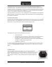
The Telos Zephyr Xstream the more common pin-outs for three pin XLR inputs & outputs. You
can easily remember the correct signals when wiring connectors using the phrase “George
Washington Bridge.” Pin 1 = G = Ground, Pin 2 = W = “+” = White (typical color in mic
cable, if there is no white there will be a red conductor), and Pin 3 = B = “-” = Black.
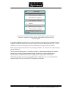
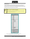
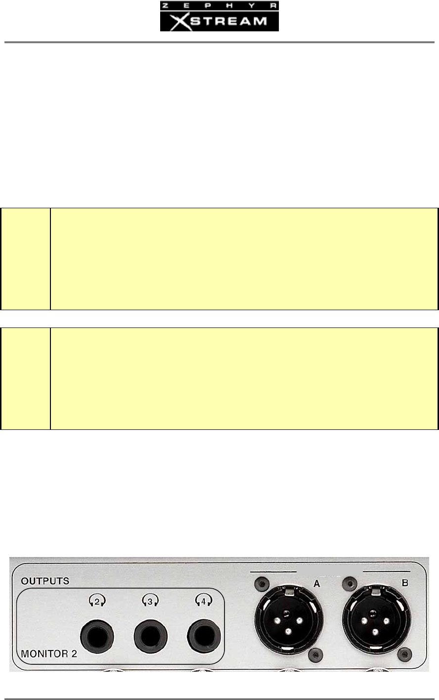
Local Monitor Mix 1 Outputs
SeetheSection3.3forinformationonthisheadphoneleveloutput,locatedonthefrontpanel.
OnunitswithrevFaudioboardsthismixcanbeoutputontheXLRsinsteadofLocalMonitor
Mix2.
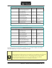
Local Monitor Mix 2 Outputs
MONITOR MIX