


USER’S MANUAL
Section 3: GUIDED TOUR of the HARDWARE 35
h
HOT TIP!
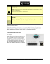
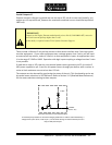
The signal fed to these inputs should normally be a mix-minus or those monitoring from the far
end will hear a delayed version of their own audio coming back to them (i.e. an echo).
See Section 10.3 for details on dealing with delay and mix-minus.
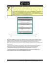
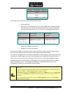
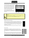
Adigitalgainadjustmentcanbeusedtoalterthesignallevelsintothecodersection.Levelscan
beincreasedbyupto12dBordecreasedbyupto12dBtoallowforequipmentvariationor
differingheadroomrequirementsatthefarend.ThisistheGainTrimselectionoftheAU
DIO
menu.Notethatbyadjustingthesignalatthispoint,youwilldecreasesystemdynamicrange
byacorrespondingamount.
?
CURIOSITY NOTE!
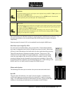
The Telos Zephyr Xstream uses the more common pin-outs for three pin XLR inputs & outputs.
You can easily remember the correct signals when wiring connectors using the phrase
“George Washington Bridge.” Pin 1 = G = Ground, Pin 2 = W = “+” = White (typical color
in mic cable, if there is no white there will be a red conductor), and Pin 3 = B = “-” = Black.
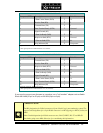
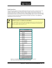
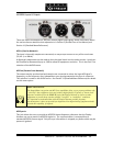
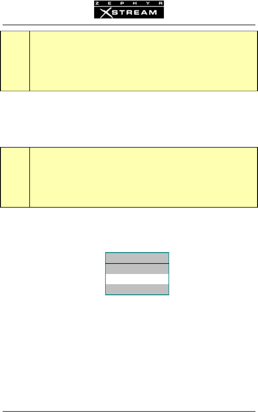
Outputs(ReceivefromNetwork)
TheseareXLRmalesocketswiththefollowingpinouts.
PIN FUNCTION
1 Ground
2 Audio +
3 Audio -
Theanalogaudiooutputshavethefollowingcharacteristics:
• Activedifferential
• LineLeveloutput.AmenuselectionLevelOutintheAUDIOmenuallows
adjustmentforConsumer(‐11dBu)orProfessional(+4dBu)levels.
• Clippoint:18dBabovenominallevel
• Impedance:<35Ohmx2
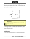
Ifasingl
e‐ended(unbalanced)outputisrequired,connectbetweengroundandeitherofthe
outputpins.Donotgroundtheunusedpin.Usethesamepinonbothoutputstomaintain
phase.