


USER’S MANUAL
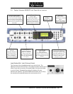
Section 3: GUIDED TOUR of the HARDWARE 33
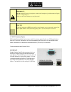
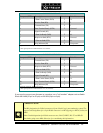
ParallelInputs0‐7
Allinputsarespeciallytreatedtoaccepteitheravoltage(upto24VDC),oraclosuretoground,
whichmaybeprovidedbyswitches,relays,orlogicoutputs.Theinputsareactivelow.Inother
words,shortingtheinputtogroundcausesittobecometrue(i.
e."asserted").
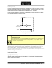
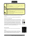
Abuiltin1kΩpullupresistorisprovidedsoTTLoutputscanbedirectlyinterfaced.Seebelow
forasimplifiedschematicoftheinputcircuitry.
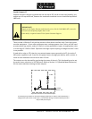
+5 VDC
(30 Volts max)
INPUT
PIN 25
Parallel logic input circuit
t
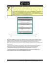
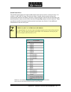
DEEP TECH NOTE!
The Zephyr Xstream’s “universal” logic input circuit (motherboard rev G and later) can be
used with switch or relay closures, voltage levels up to 24 Vdc, or logic outputs – either
“totem-pole” or open-collector.
TheinputscanbetransmittedtothefarendZephyrXstreamwhenusingtheLayer‐3,AAC,or
AAC‐LDcodingmodes.Theinputscanalsobeusedforlocalcontrolfunctionalitysuchas
triggeringDialSetups(PanicDial).RefertoSection11.5(DetailedMenuReference)forthemenu
selectionsrelatingtothesefunctions.
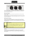
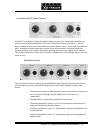
Analog
Inputs & Outputs
Inputs(SendtoNetwork)
TheseareComboConnectorswithXLRfemaleand¼”Tip‐Ring‐Sleeve(TRS)balancedfemale
inputs.Thepinoutisasfollows: