


1.3 SYSTEM BASICS
18 Installation Manual
Note
Ports 1-12 are at TNV.
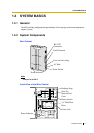
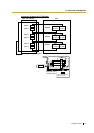
System Components
Power Indicator:
Indicates the system status: when flashing, the system is off-line (not ready to receive calls).
RS-232C Connector:
Connects an ASCII or VT terminal to the VPS that is necessary to program the system.
Earth Terminal:
Should be connected to an earth source with less than 1 resistance.
Fuse:
Protects the system from power line surges and should only be replaced with the same type.
Please see the fuse socket on the cabinet for the value of the fuse.
AC Inlet:
Connects the power cable to an AC outlet dedicated to the VPS.
Power Switch:
Starts the system and begins the self-test.
SAFETY PRECAUTION: When making any connections or removing the cover, be sure
the power switch is switched off.
Earthing Strap:
Protects the printed circuit board from static electricity.
(Earth) SAFETY PRECAUTION: Discharge any body static by touching the metal bar.
Optional Port Cards:
The following types of port cards can be installed in the VPS.
• Four digital port expansion cards (KX-TVP204)
• Two digital/analogue port expansion cards (KX-TVP102)
KX-TVP102 consists of the following 2 cards:
• Telephone line interface card
• Digital processor (DSP) card
The telephone line interface transmits and receives analogue and digital signals to and from
the telephone line. The analogue input signal is digitised at a sampling rate of 8 kHz to
create a 16-bit digital signal.
The DSP has the following features:
• Voice Compression and Decompression
• Touchtone Detection
• Touchtone Generation
• Call Progress Tone Detection
KX-TVP204 consists of a telephone line interface and a DSP. The telephone interface of the