


DCS SPECIAL APPLICATIONS
COMBINED PROGRAMMING MANUAL NOVEMBER 2001
3–12
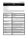
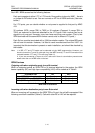
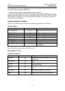
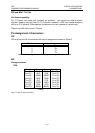
Supported ISDN supplementary services
Service Note
DDI PRI DDI Mode and BRI T P-P DDI
MSN BRI T P-M MSN
CLIP Incoming call and outgoing call
Sub Addressing Sub-address of incoming / outgoing call
AOC
ETSI AOC-D Currency/Unit
ETSI AOC-E Currency/Unit
Italy
Holland
Portugal
Belgium
Table 5 – Supported ISDN supplementary services
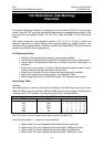
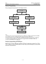
Installation
The installation procedure is as follows:
1) Switch off the power to the system.
2) Insert the card in the appropriate slot.
3) Execute MMC 811 (Reset System).
4) Carry out related MMC programming according to your intended use of the card.
5) Run MMC 418 (Card Restart).
Note:
§ In DCS, both BRI and PRI must be installed in the Basic Key Service Unit (not the Expansion
Cabinet).
§ The PRI card must be installed in the first slot with the next even-numbered slot empty.
§ 100Ω line termination may not be present on the BRI card. If not, termination should be provided
somewhere outside the BRI card.
§ In BRI, LT-T and LT-S mode can be selected only by MMC programming. However, you should
connect the Tx and Rx cable pair from MDF correctly. Tx and Rx connections are reversed be-
tween LT-T and LT-S mode (see Table 15).
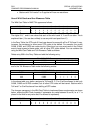
Operation
Ports
After installation, the system allocates a port number to each B-channel in exactly the same
way as the analogue trunk case. Thus, a BRI will be assigned eight port numbers, while a
PRI will be assigned 30.
Note: To avoid confusion, the words "port" and "access" are used here with different meanings. "Port"
is used to specify one B-channel, while "access" specifies one BRI span which consists of two B-
channels and one D-channel.