


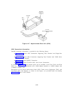

Connectivity Figures
Figures 4-21 through 4-31 provide connection information for various equipment. These
figures have been included as an aid to understanding how equipment can be connected to
System 25 and to indicate required connecting and supporting equipment. Other
arrangements are possible; these figures
can be useful in developing connecting
arrangements for new or customer-provided equipment.
The PEC codes have been noted on the figures, as have indications of the source for
obtaining non-PEC equipment (eg, from installer or furnished with other equipment). This
information can be of use to Account Executives and Technical Consultants who are adding
equipment to existing installations.
For new installations, the DOSS Configurator must be
used to select equipment requirements.
For existing installations, you will need to determine
what equipment is already installed.
Y
OU should not order equipment directly using the
PECs in these figures.
The octopus cable (PEC 2720-05P), for example, supports eight
terminals; you do not order one per terminal.
A list of related PECs, Apparatus, and Comcodes is provided in Section 7. Be sure to check
the Sales Manual and/or DOSS before ordering since this information changes frequently.
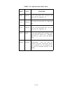
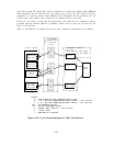
Symbols Used in Figures:
Modular jacks are shown by the triangle symbol. The 25-pair
connectors are indicated by shaded blocks.
Generally, only one leg of an octopus cable is
shown. Unterminated wiring requiring cut down or other termination do not have symbol
designations.
The 103A Connecting Block is a typical modular wall jack that provides cut-
down connections for building (station) wiring.
Voice Terminal and Adjunct Connections
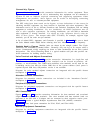
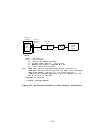
Figures 4-21 through Figure 4-27 provide connection
information for single-line and
multiline voice terminals.
The single-line terminals can be located on-premises, off-
premises, or out-of-building. The 7300H series multiline voice terminals can be used for out-
of-building service but must be within 2000 feet of the system cabinets (local power is
required beyond 1000 feet). Off-premises service is not available.
Diagrams for voice terminal adjunct connections are integrated with the specific feature
descriptions in Section 2.
Attendant Console Connections
Diagrams for attendant console connections are included in the “Attendant Console”
descriptions in Section 2.
Peripheral Equipment Connections
Diagrams for peripheral equipment connections are integrated with the specific feature
descriptions in Section 2.
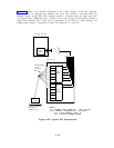
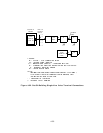
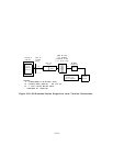
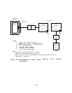
ADU Connections
Figures 4-28 and 4-29 provide connection information for data terminals and associated
single-line or multiline voice terminals.
The voice terminal and data terminal leads are
separated at the SIP with a Y-adapter and are connected to their respective station ports.
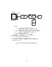
Figure 4-30 presents a typical Multiple Asynchronous Data Unit (MADU) connection.
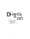
Figure 4-31 shows local power connections for Z3A1, Z3A2, and Z3A4 ADUs.
Auxiliary Equipment Connections
Diagrams for auxiliary equipment connections are integrated with the specific feature
descriptions in Section 2.
4-51