


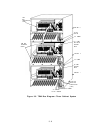
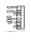
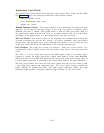
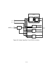
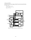
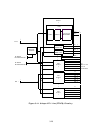
Ground Start Trunk (ZTN76)
The Ground Start Trunk Circuit Pack interfaces eight central office trunks and the TDM
bus. Figure 3-8 shows the following Ground Start Trunk unique circuitry:
● Ground detector circuit
● Port Input/Output (I/O) circuit
● Eight port circuits.
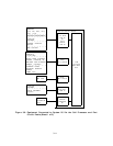
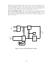
Ground Detector Circuit:
The ground detector circuit determines if ground has been
applied to the tip lead for incoming seizure.
It also senses tip ground on outgoing seizure
indicating dial tone is present.
One ground sensor is used for each port circuit. Input for
the ground sensor comes from the port circuit as an analog current to the -48 volt dc supply.
The output of the ground sensor is a port control point to the port 1/0 circuit.
Port I/O Circuit:
This circuit consists of bus expanders for communication between the
on-board microprocessor and the port circuits.
It receives commands from the on-board
microprocessor and distributes them to the individual port circuits. It also accesses the port
circuit scan points and passes the information to the on-board microprocessor.
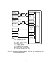
Port Circuits:
The eight port circuits are identical.
Each port circuit consists of a
coder/decoder (codec), hybrid circuit, line transformer, relay driver, and surge protection
circuit.
The codec is a 4-wire circuit that converts the NPEs digital output to an analog signal.
Likewise, it converts the analog signal from a central office trunk to a Pulse Code Modulated
(PCM) data signal to the NPE. The hybrid circuit converts the codec 4-wire analog signal to
a 2-wire analog signal that is connected to the central office trunk by the line transformer.
The relay driver buffers and inverts the relay drive signals from the port 1/0 circuit so that
a logic high input operates the appropriate relay.
The relays control circuitry provides the
proper signaling for ground start trunks.
The trunks support touch-tone dialing. The surge
protection circuit provides overvoltage lightning surge protection for the circuit pack.
3-16