


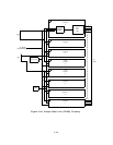
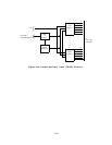
Ringing Application Circuit: This circuit receives ringing voltage from the power supply.
It monitors ringing voltage and current, generates signals to the on-board microprocessor
indicating zero ringing voltage and current, and detects a terminal user lifting the receiver
during ringing.
This prevents the application of ringing to the port circuit when a terminal
user lifts the receiver during the ringing phase.
Maintenance circuitry is also included. The
maintenance circuitry detects when a terminal is connected to the port circuitry and checks
for faults in the ringing application circuitry.
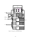
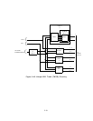
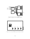
Port I/O Circuit:
This circuit consists of bus expanders connecting the on-board
microprocessor
and the port circuits.
It receives
commands from the on-board
microprocessor and distributes them to the individual port circuits. It also accesses the port
circuit scan points and passes the information to the on-board microprocessor.
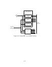
Port Circuits:
The eight port circuits are identical.
Each port circuit consists of a
coder/decoder (codec), hybrid circuit,
electronic battery feed circuit, ring relay, and
overvoltage surge protection circuit.
The codec is a 4-wire circuit that converts the analog signal from a voice terminal to a PCM
data signal.
It converts an incoming PCM data signal from the NPEs to an analog signal.
The hybrid circuit converts the 4-wire analog signal from the codec to a 2-wire analog signal
that is connected to the analog line.
Filtered power is provided for the codec and hybrid
circuits.
The electronic battery feed circuit provides talking battery to the voice terminal. It also
produces a controlled de battery feed for short and long loops, detects tvhen a receiver is
lifted, and provides the message waiting signal by periodically turning off the feed voltage.
The ring relay provides the interface between the ringing application circuit and the port
circuit. It causes ringing turn on and turn off.
The overvoltage surge protection circuit provides lightning surge and power line cross
protection for the circuit pack.
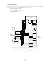
Note: The TN742 can be used instead of the ZTN78 Tip Ring CP. The TN742 supports
up to five bridged single-line voice terminals, however, only two can be off hook at one
time. The ZTN78 CP does not support bridged terminals. In addition, the TN742
supports out-of-building, extended, and off-premises stations, the ZTN78 does not.
3-29