


Loop Start Trunk (ZTN77)
The Loop Start Trunk Circuit Pack interfaces eight central office loop start trunks and the
TDM bus.
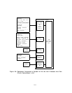
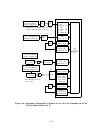
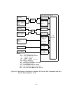
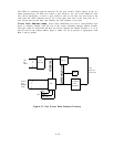
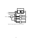
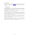
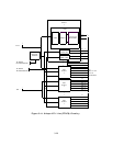
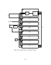
Figure 3-9 shows the following Loop Start Trunk unique circuitry:
● Port Input/Output (I/O) circuit
● Eight port circuits.
Port I/O Circuit: This, circuit consists of bus expanders for communication between the
on-board microprocessor and the port circuits.
It receives commands from the on-board
microprocessor and distributes them to the individual port circuits. It also accesses the port
circuit scan points and passes the information to the on-board microprocessor.
Port Circuits: The eight port circuits are identical.
Each port circuit consists of a codec,
hybrid circuit, line transformer, relay driver, and surge protection circuit.
The codec is a 4-wire circuit that converts the NPEs output to an analog signal. Likewise, it
converts the analog signal from a central office trunk to a PCM data signal to the NPE. The
hybrid circuit converts the codec 4-wire analog signal to a 2-wire analog signal that is
connected to the central office trunk by the line transformer.
The relay driver buffers and inverts the relay drive signals from the port 1/0 circuit so that
a logic high input operates the appropriate relay.
The relays control circuitry provides the
proper signaling for loop start trunks. The trunks support touch-tone dialing and dial pulse
signaling. The surge protection circuit provides overvoltage lightning surge protection for
the circuit pack.
3-18