


Two time slots are required for each 2-party conversation.
Each party transmits (talks) on
one time slot and receives (listens) on another. Only five parties are allowed in a conference.
During a conference connection, each member of the conference transmits on an individual
time slot while receiving on as many as four other time slots.
The actual switch capacity is
115 simultaneous 2-party conversations).
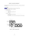
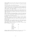
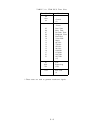
Table 3-A shows the allocation of the 256 time slots. Five are used for system control, 15 for
tones, 235 for call processing, and one is not used.
Physical Characteristics
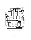
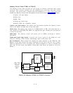
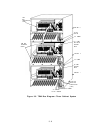
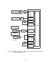
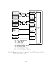
The TDM bus is an 8-bit bus. The bus snakes continuously between cabinets in a
multicabinet system as shown in Figure 3-5. The total length is about 9 feet for a three
cabinet system.
The bus is driven from any of the circuit packs in the cabinets.
Similarly, a signal on the bus can be received by any circuit pack.
Within a cabinet, the bus is printed on one side of the circuit pack carrier backplane
while the other side is solid ground.
Ribbon cables are used to cable the TDM bus
between cabinets in a multi-cabinet system.
Electrical Characteristics
The TDM bus is an unbalanced, low characteristic impedance transmission line. Paths
printed over a ground plane on the carriers and the flat ribbon cables between carriers
maintain this impedance level over the full length of the bus.
One end of the bus is terminated to ground with a bus termination circuit card and the
other end is terminated by a network on the ZTN81B or ZTN127 Memory CP. Each
circuit pack connects to the bus through a custom bus driver device. The bus driver is a
switchable constant current source so that even in the “high” output state there is no
bus loading to cause reflections.
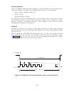
The current output of the drivers is adjusted so that
logic “high” is 1.5 volts compared to a “low” of 0 volts.
3-7