


following characteristics:
Display: The minimum display size is 16 lines by 80 columns. The port provides both
carriage return and line feed characters to position the cursor at the start of the next line.
Destructive scrolling is also expected (new lines added at the bottom of the screen and top-
most lines disappear). Full duplex operation is required.
Alphabetic ASCII characters in
both upper-case and lower-case will be sent to the SAT, along with ASCII numerals and
some basic ASCII symbols. The device used must be capable of displaying ASCII alphabetic
characters when either upper-case or lower-case characters are received. However, upper-
to-lower case mapping (or vice-versa) for display is acceptable since no meaning is associated
with case.
Keyboard: The administration port requires ASCII alphanumeric characters as well as
some symbol characters.
If the keyboard generates only upper-case or only lower-case
alphabetic characters the administration port will respond appropriately, since upper and
lower case input is considered identical. The SAT should be capable of sending the following
ASCII Characters:
A-Z or a-z
0-9
*,#
.
?
BACKSPACE
RETURN
“ (V2)
The data transfer
administration port.
Refer to the
System
information.
rate is set when a carriage return character is received by the
There are two supported transfer rates: 1200 bps and 300 bps.
25
Administration Manual for administration procedures and additional
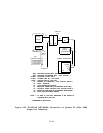
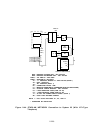
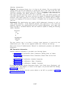
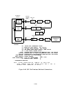
SAT Connection Information
Detailed connection information is provided in the following figures:
●
Figure 2-46–SAT On-Premises Direct Connections (Sharing Same AC Outlet)
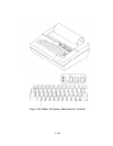
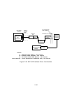
● Figure 2-47—SAT On-Premises Direct Connections (Greater Than 50 Feet from
System Cabinet)
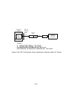
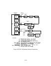
● Figure 2-48—SAT On-Premises Switched Connections
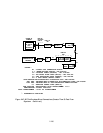
● Figure 2-49—SAT Off-Premises Direct Connections
● Figure 2-50—SAT Off-Premises Switched Connections
Descriptions of the SIP (Station Interconnect Panel), TAE (Trunk Access Equipment), and
associated cables and adapters, as shown on the figures, are provided under the heading
“Connectivity” in Section 4.
Maximum cabling distances from the system cabinets to the SAT are provided in Section 5,
“Technical Specifications.”
2-227