


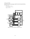
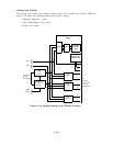
Data Line (TN726)
The Data Line Circuit Pack interfaces eight Asynchronous Data Units (ADUs) data devices
and the TDM bus.
The ADUs are typically, in turn, connected to RS-232 type devices.
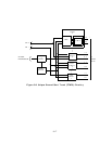
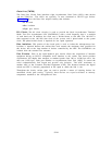
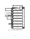
Figure 3-12 shows the Data Line unique circuitry that includes:
● A bit clock
● Bus isolation
● Eight port circuit.
Bit Clock: The bit clock circuitry is used to provide the Octal Asynchronous Terminal
Mode Two EIA Asynchronous LSIs (OATMEALs) with a clock frequency that is a multiple
of each baud rate. In addition, the clock rate is divided down to 160 kHz. The 160 kHz is
then compared to the 160 kHz data clock of the system, and is phase-locked to the system
clock. The phase-locked circuit is required for low speed operation.
Bus Isolation: This portion of the circuit pack is used to isolate the microprocessor bus.
Isolation is required because the realized bus load exceeds the maximum limit specified for
this device, due to the large number of devices controlled by the NPE. The OATMEALs are
isolated from the common bus structure.
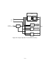
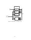
Port Circuits.
Each of the eight identical port circuits allows the connection of interface
equipment having an RS-232 compatible serial interface to the switch. The circuit provides
asynchronous full duplex data transport at standard speeds from 300 to 19,200 bps and a low
data rate (<300 bps). Each port includes an Asynchronous Data Unit (ADU) to extend the
serial communications link length and provide safe isolation.
The ADU terminates to
another ADU at the Customer Provided Equipment (CPE). The distance between the digital
switch and CPE is inversely proportional to the speed at which the link is run.
Throughout the circuit, various gates are used to provide a means of isolating devices for
automated circuit pack testing.
Typically, these devices are crystal oscillators or memory
components attached to the microprocessor bus.
3-24