


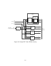
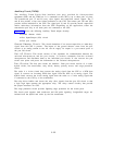
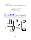
generator and time slot table circuits with the TDM bus.
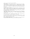
Tone Generator:
The tone generator consists of a digital signal processor (DSP), a
counter, and a dual-port tone RAM. The DSP operates at 10 MHz and produces .24 different
tones. The dual-port tone RAM stores these tones in 24 different addresses. The counter
under control of the tone clock causes the DSP to transmit one sample of each tone every 8-
kHz. The counter is synchronized to the TDM bus and is offset to provide delay needed for
access time.
Time Slot Table and Counter: The time slot table consists of a dual-port time slot table
RAM and a counter. The dual-port RAM (DPRAM) contains 256 different addresses. These
addresses correspond to the time slots on the TDM bus. The counter sequences through the
time slot table addresses in the dual-port RAM and causes the proper tone(s) to be output by
the dual-port tone RAM on TDM bus time slots.
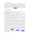
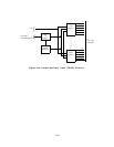
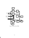
Tone Detector Ports: The Service Circuit CP provides four Dual Tone Multifrequency
(DTMF) detector port circuit interfaces via the TDM bus. Each port circuit is connected to
an NPE serial input and output.
Ports 0, 1, 2, and 3 are DTMF tone detectors with NPE
loop-around paths.
The four port circuits contain a DSP, NPE to DSP interface circuitry, a DSP restart circuit,
and an interrupt generator. One DSP implements two tone receivers.
The TDM bus signals are connected to the DSP in serial form from the NPEs by the DSP
interface circuit. The DSP controls the output clocking of the NPE. The system framing
signal is synchronized and connects to the DSP.
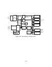
Port I/O and Sanity Check Circuit: This circuit interfaces the on-board microprocessor
to the port circuits and checks the sanity status of the DSPs of the port circuit.
3-39