


DIRECT GROUP CALLING DELAY ANNOUNCEMENT
Description
Provides a recorded announcement to an outside (trunk) caller who has been placed in queue
for a DGC Group.
When all members in the group are busy (off-hook), the call will be queued for DGC service
and the calling party will receive ringback tone.
Note that no incoming call indication
(ringing) is provided to the DGC group members at this point. After a specified number of
rings (administrable) a recorded announcement will be played to the calling party without
disturbing his or her position in queue.
The caller is subsequently placed on hold and will
receive music if available.
Once a call begins to ring at a DGC station, the call is no longer eligible for delay
announcement service.
The call will then ring until answered, covered, picked up or
abandoned.
Considerations
DGC Delay Announcements provide the calling party with a message that acknowledges
their call and assures them that their call will be handled in an orderly way.
Interactions
● Tie Trunks: Calls to busy DGC groups via auto-in tie trunks w-ill he queued, but
will not receive the delay announcement. Calls to busy DGC groups via dial-in tie
trunks will not be queued (and, hence, will not receive the delay announcement).
Administration Requirements
The DGC announcement device requires a port assignment on a ZTN78 Tip Ring Line or
TN742 Analog Line CP. Only one DGC Delay Announcement may be assigned in the system.
Callers to all DGC groups receive the same message.
Hardware Requirements
The AT&T Answer-Record 2500 or Code-A-Phone 2540 may be used as the announcement
device.
The announcement device
must automatically hang up at the end of each call so that
the incoming call can be returned to the DGC queue.
The equipment requires a port on a ZTN78 Tip Ring Line (or TN742 Analog Line) CP. The
system supports one DGC delay announcement.
For Music-On-Hold hardware information, refer to the “Music-On-Hold” feature description.
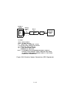
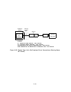
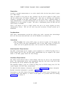
Detailed connection information is provided in Figure 2-23.
Descriptions of the SIP (Station Interconnect Panel), TAE (Trunk Access Equipment), and
associated cables and adapters, as shown on the figures,
are provided under the heading
“Connectivity” in Section 4.
2-125