


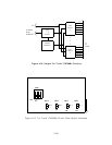

Tone Detector (TN748)
The Tone Detector Circuit Pack provides four touch-tone receivers and two general purpose
tone receivers that detect appropriate system and network tones on the TDM bus.
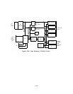
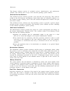
The Tone Detector CP consists of the same common circuitry as the intelligent port circuits
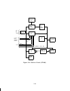
and the following unique circuits (see Figure 3-20):
● Port I/O circuit
● Port or DSP Sanity check circuit
● Four touch-tone port circuits
● Two general purpose tone detector ports
● Two NPE loop-around test ports.
Up to a maximum of two Tone Detector CPs can be provided in the system.
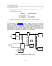
Port I/O and Sanity Check Circuit: This circuit interfaces the on-board microprocessor
to the port circuits and checks the sanity status of the port circuits Digital Signal Processors
(DSPs).
Port Circuits:
There are eight port circuits. Six port circuits are connected to Network
Processing Elements (NPEs). Port circuits 0,1, 4, and 5 are DTMF tone detector ports. Each
of the six port circuits has an associated Digital Signal Processor (DSP), NPE to DSP
interface circuitry, a DSP restart circuit and an interrupt filter. Port circuits 2 and 6 are
general purpose tone detector ports.
Port circuits 3 and 7 provide digital Ioop-back testing of
each NPE on the circuit pack.
The NPE serializes TDM bus signals that are connected to the DSP in serial form from the
NPEs by the DSP interface circuit. Serial clock and data signals connect directly from the
NPE to the DSP. The system framing signal is synchronized and connects to the DSP.
The DSP restart circuit controls the DSPs. When the on-board microprocessor is not
functioning properly, the DSP restart circuit takes all of the DSPs out of service. It restarts
each individual DSP under control of the port 1/0 and sanity check circuit.
The touch-tone DSPs, under control of the on-board microprocessor, write data
synchronously to the NPEs. The interrupt filter detects valid touch-tone signals and allows
end-to-end transmission while blocking end-to-end touch-tone signaling.
3-41