


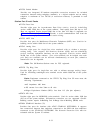
Cabinet
1
(Control and Port Circuits)
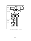
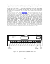
Cabinet 1 (Figure 4-3) is always required.
It provides mounting space for 12 CPs and can
support a small telecommunications system (eg.,
50 to 60 stations and 10 to 15 trunks). It
contains a Memory and Call Processor that together are referred to as the Common Control
(CC), a Service Circuit, and up to 9 port CPs.
The Memory, Call Processor, and Service
Circuit must be mounted in CP slots 1, 2, and 3, respectively. Slots 4 through 12 (9 total)
provide mounting for the various port CPs that can be used. Any port CP can be mounted in
any of these 9 slots. The Memory and Call Processor are electrically linked by a ribbon cable
(Front Plane B
US) that loops between their front edges. The Tone Detector and Pooled
Modem CPs of the system (referred to as System Resource Cl’s ) can also be mounted in the
port CP slots. Circuit packs are described in this Section under the heading “Circuit Packs”.
Cabinet Address Plug
An address plug is provided on the middle of the backplane of each cabinet (accessible after
removing the top rear cover) and is used to designate the cabinet number to the software.
When plugged into the designated area at CP slot 5, the cabinet is identified as Cabinet 1; at
slot 6 as Cabinet 2, and at slot 7 as Cabinet 3.
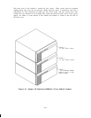
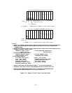
Cabinets 2 and 3 (Port Circuits)
Cabinet 2 and Cabinet 3 (Figure 4-3) can be provided. The cabinets provide mounting space
for additional port CPs (12 maximum each) required for larger systems. The Tone Detector
and Pooled Modem CPs can also be mounted in these cabinets.
These cabinets are simply
stacked on top of Cabinet 1.
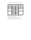
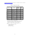
Table 4-A summarizes port CP capacity of 1-, 2-, or 3-cabinet systems.
4-4