


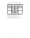
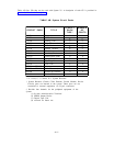
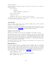
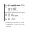
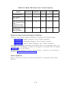

Table 4-B lists CPs that can be used with System 25. A description of each CP is provided in
Section 3, Functional Description.
TABLE 4-B. System Circuit Packs
CIRCUIT
NUMBER
CIRCUIT PACK
TITLE
PACK OF
TYPE *
PORTS
TN726
Data Line
P
8
TN735
MET Line
P4
TN742
Analog Line
P8
TN748
Tone Detector †
R 4
TN753
DID Trunk
P8
TN758
Pooled Modem R 2
TN760B
Tie Trunk
P 4
TN763
Auxiliary Trunk P 4
ZTN76
Ground Start Trunk P 8
ZTN77
Loop Start Trunk
P
8
ZTN78
Tip Ring Line
P
8
ZTN79
ATL Line
P 8
ZTN81 or ZTN127 Memory
C
ZTN82 or ZTN128 Call Processor ‡
C
ZTN84
STARLAN Interface P 4
ZTN85
Service Circuit R 4
* P = Port, C = Control, R = System Resource.
† System Resource Circuits (Tone Detector, Pooled Modem, Service
Circuit) ports are internal to the system. These ports are not
connected to external equipment via 25-pair connectors.
‡ Provides four channels for the peripheral equipment of the
system:
(1) System Administration Terminal
(2) SMDR Output Device
(3) Digital Tape Unit
(4) reserved for future use.
4-11