


Tie Trunk (TN760B)
The Tie Trunk Circuit Pack interfaces four 6-wire tie trunks and the TDM bus. Two tip and
ring pairs form a 4-wire analog transmission line.
An E and M pair are used for signaling.
The T and R pair transmit analog signals from the circuit pack. The T1 and RI pair receive
analog signals from the tie trunk.
The E and M pair are dc signaling leads used for call
setup handshaking.
The E lead receives signals from the tie trunk and the M lead provides
signals from the circuit pack.
The TN760Bs four port circuits support Type I, Type I
Cornpatible, or Type V signaling.
Incoming and outgoing trunks can be either automatic,
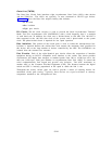
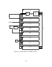
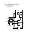
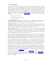
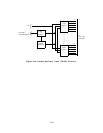
immediate start, wink start, or delay dial. Figure 3-16 shows the following Tie Trunk unique
circuitry:
● Ground detector circuit
● Port Input/Output (1/0) circuit
● Four port circuits.
Ground Detector Circuit: This circuit determines if a ground has been applied to the E
lead. Ground detector inputs come from the port circuits as an analog current to the -48 volt
dc supply. Its output is a port control point to the port I/O circuit.
Port I/O Circuit: This circuit consists of bus expanders for communication between the
on-board microprocessor and the port circuits.
It receives commands from the on-board
microprocessor and distributes them to the individual port circuits. It also accesses the port
circuit scan points and passes the information to the on-board microprocessor.
Port Circuits: The port circuits are identical, except for port 3 where part of the E-lead
maintenance circuit is located. Each port circuit consists of a codec with associated input
and output line transformers,
analog operational amplifiers, a power filter, loop-around
transistors, port control comparators, a relay driver, an electronic power feed device, an E-
lead test maintenance circuit, and surge protection circuits.
The codec converts the incoming 4-wire analog signal from the tie trunk to a PCM data
signal. The codec converts the incoming PCM data signal from the NPE to an analog signal.
Outgoing and incoming line transformers provide de isolation to the tip and ring leads.
Analog operational amplifiers provide amplification and buffering for the codec and network
and loop-around gain compensation.
Filtered power is provided to the codec and amplifiers.
The loop-around transistors are under control of the port control comparators and provide a
loop-around path for the signal for testing purposes.
The relay driver buffers and inverts
the relay drive signals from the port 1/0 circuit so that a logic high input operates the
appropriate relay.
The relays and electronic power feed device control the M-lead circuitry
to provide the proper signaling handshake for call progress tones and dial pulse dialing.
The electronic feed device provides a -48 volt de current to the M-lead circuits. It also tests
the M-1ead circuits for opens or shorts and prevents uncontrolled operation during power-up.
The E-lead test circuit provides a ground to the ground detector circuit for testing purposes.
The surge protection circuitry provides lightning surge and power cross protection for the
circuit pack.
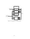
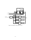
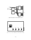
For each port circuit, E&M/Simplex and surge protection are selected by
switch settings as shown on Figure 3-17.
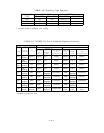
The signaling type is administrable for each port.
Table 3-B summarizes the conditions
present as the transmit and receive control signals for each signaling type. Table 3-C lists
the preferred TN760B tie trunk signaling format to be used in the likely-to-be-encountered
installation situations.
3-32