


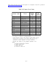
Circuit Pack Features
All system CPs have the following features:
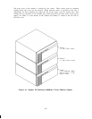
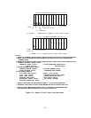
● Solid-state circuitry mounted on 7.6 by 14.1-inch printed wiring board (TN-type)
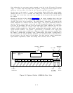
● Color coded face plate labels identify the CP type and function (White = Control,
Purple = Port or System Resource)
●
Individual circuit functions all contained on one CP
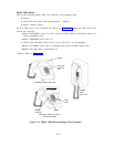
● Metal tab for grounding
● Locking tab-type handle provides easy insertion or removal of a CP
● Port CPs can be inserted or removed with power “On” and the system processing
calls. Only the calls utilizing circuits on a removed CP will be affected.
Note: Power must be turned off when replacing the following CPs:
—
Memory (ZTN81 or ZTN127)
—
Call Processor (ZTN82 or ZTN128)
—
Service Circuit (ZTN85)
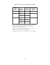
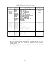
● Status LEDs
—
Port CPs:
● Red—“On” several seconds during power up and test, “Off” with test
pass. After test pass, “On” if fault in CP is subsequently detected.
● Green—“On” indicates resource available (port is translated)
● Yellow—“On” indicates a call in progress. “Off” when not in use.
● All LEDs “Off’’—CP is not translated.
—
Common Control CPs:
● Memory CP: Red status LED only.
“On” several seconds during power up and test, “Off” with test pass.
After test pass,
“On” if fault in CP is detected.
● Call Processor CP: Green Status LED only.
“Off” for several seconds during power up and test, then lamp flashes
to indicate an “OK” state. Steady “Off” or “On” indicates a problem.
—
System Resource CPs:
● Service Circuit CP:
Similar to port CPs except yellow LED flashes to show system clock is
active and is steadily
“On” when a tone receiver is in use. “Off”
indicates a problem.
● Modem Pool and Tone Detector CPs:
Same as Port CPs.
4-10