


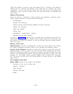

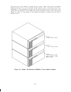

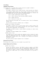
Each cabinet has its own power supply mounted to the left of the CP carrier. The power
supply is 3 inches wide and weighs about 9 pounds.
Voltage and current supplied to the
carrier are: +5 V dc at 35A, -5 V dc at 3A, -48 V dc at 3A, and 90 V ac at 0.16A.
On the front of the supply is a green Light Emitting Diode (LED) that, when lighted,
indicates that the +5 V de is available and within limits.
The LED can be viewed through
the slotted area on the front cover, and is just behind the fan located at the top left edge of
the cabinet.
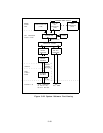
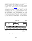
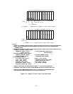
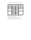
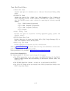
Mounted on the back of the cabinet (Figure 4-2) is the copper grounding block with four
terminating positions,
an AC input power receptacle,
(0)=OFF] and twelve 25-pair connectors.
a power On/Off switch [(l)=ON,
The ground block is connected to DC ground on the
carrier backplane at a location near the power supply.
The 25-pair connectors provide an
interface between cross-connect wiring and the CPs immediately behind each connector.
Two slots are provided in the rear cover just above the 25-pair connectors for the Time
Division Multiplex (TDM) bus extender cable.
The TDM cable is used to connect 2- or 3-
cabinet systems together in a daisy-chain configuration and provides control and data
signals between Cabinets.
The Cabinet 1 ground block is connected to the single point
ground of the system using 6 AWG wire.
Separate 6 AWG wires are then connected from
the Cabinet 1 ground block to Cabinet 2 and 3 ground blocks. The Cabinet 1 ground block is
also connected to the Coupled Bonding Conductor.
An information label is provided across
the top portion of the rear panel on each cabinet.
The label provides cabinet identification,
input electrical requirements, caution and warning notes, and FCC and UL labels.
CAUTION & WARNING GROUNDING
LABELS
FCC LABEL
BLOCK
SYSTEM 25
❑
120
VOLTS AC
J58901A
❑
6
AMPS
HZ
❑
60
❘
❘ ❘
12
11
10 9 8 7
6
5
4
3
2
1 ❍ ❍ ❍ ❍
25-PAIR
INPUT
ON/OFF
CONNECTORS
AC POWER
SWITCH
RECEPTACLE
Figure 4-2. System Cabinet (J58901A)—Rear View
4-3