


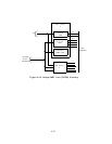
Auxiliary Trunk (TN763)
The Auxiliary Trunk Circuit Pack interfaces four ports provided for client-provided
equipment (CPE) and the TDM bus. It is connected to the CPE by up to three pairs of wires.
The transmission pair (T and R) carry voice signals and touch-tone control signals. The T
and R also provide a loop start seizure indication to the CPE. The seizure pair (SZ and SZ1)
provide seizure indication to the CPE. The signal pair (S and S1) provide answer supervision
and/or make-busy information from the CPE. Depending on the application, either the
transmission pair only or all three pairs are connected to the CPE.
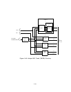
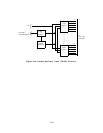
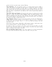
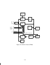
Figure 3-18 shows the following Auxiliary Trunk unique circuitry:
● Ground detector circuit
● Port Input/Output (I/O) circuit
● Four port circuits.
Ground Detector Circuit: This circuit determines if an answer-supervision or make-busy
signal from the CPE is present.
The inputs of the ground detector come from the port
circuits as an analog current to the -48 volt de supply. Its output is a port control point to
the port I/O circuit.
Port I/O Circuit: This circuit consists of bus expanders for communication between the
on-board microprocessor and the port circuits.
It receives commands from the on-board
microprocessor and distributes them to the individual port circuits. It also accesses the port
circuit scan points and passes the information to the on-board microprocessor.
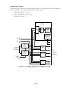
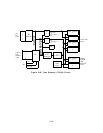
Port Circuits: The four port circuits are identical.
Each port circuit consists of a codec,
hybrid circuit, line transformer, relay driver, battery polarity sensor, and surge protection
circuit.
The codec is a 4-wire circuit that converts the analog signal from the CPE to a PCM data
signal. It converts an incoming PCM data signal from the NPE to an analog signal. The
hybrid circuit converts the 4-wire analog signal from the codec to a 2-wire analog signal that
is connected to the CPE by a line transformer.
The relay driver buffers and inverts the relay drive signals from the port I/O circuit so that
a logic high input operates the appropriate relay. The relays control circuitry that provide
the proper interfaces for CPE.
The surge protection circuit provides lightning surge protection for the circuit pack.
The circuit pack supports both touch-tone and dial pulse signaling. Longitudinal surges are
isolated from the hybrid and codec by the line transformer.
3-35