


DATA SERVICES OVERVIEW
System 25’s data features provide switched data transmission at up to 19,200 bps (RS-232
interface ), and a 212A modern compatible conversion resource capable of handling data at
300 and 1200 bps.
The system provides switched connections between
data endpoints. These endpoints include
data terminals, personal computers, multiport computers, and modems. Data endpoints are
either digital data endpoints or analog data endpoints.
Analog endpoints are connected to System 25 voice terminal or trunk port circuits through a
modem in the traditional manner.
Digital endpoints are connected to System 25 data port
circuits on the TN726 Data Line CP. A data module (specifically, an Asynchronous Data
Unit - ADU) is required in place of the modem used with analog endpoints. Section 4 of this
manual shows the connections supported and required connecting equipment.
Data
Calls can be set up between data endpoints.
Analog to analog and digital to digital
connections are straightforward;
calls between analog and digital endpoints are possible
only if the system is equipped with a conversion resource (TN758 Pooled Modem Circuit Pack
or external modem pool).
System 25 data calls from analog endpoints (including those to
digital endpoints) are set up in the traditional manner.
The calling party should follow the
procedures supplied with his/her modem.
However, a Modem Request Code must be dialed
when calling a digital endpoint.
Call set-up from digital endpoints is facilitated by several data features:
Command Mode,
Expert Mode, Data Terrminal Dialing, Modem Pooling, Third-Party Call Setup,
and Transfer
To Data.
In the discussion that follows, it is important to understand the difference between analog
voice terminology and data terminology.
Refer to the “Glossary” (Section 9).
The following provides a definition of a data call in terms of its contextual components. The
components are (1) data endpoints, (2) data endpoint states, (3) data call processing modes,
(4) connecting configurations, and (5) controlling features.
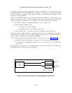
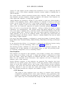
Data Endpoints
Data endpoints are composed of data equipment, a data module or modem, and a connection
to the switch via an analog or data port.
A digital data endpoint is addressed by its Data
Dial Code (DDC). Analog data endpoints are addressed like other voice terminals, by their
PDCs. For the remainder of this description,
data endpoints will refer to digital data
endpoints unless stated otherwise.
Several different categories of data endpoints are supported. The categories have been
divided into two general groups, those having a DTE type interface, which encompasses
almost all of the data terminal devices, and a group of DCE interface devices (primarily
modems ). The groups have then been divided into categories based upon their functional
attributes. However, it must be noted that within each category, control interfaces may
vary. The following describes the categories and attributes of each:
1. DTE Devices
This group of data endpoints have one thing in common: their interface
configuration (although RS-232 control signal utilization varies significantly from
terminal to terminal). Some data equipment do not use any RS-232 control signals;
these require only BA (Transmitted Data Ready-Tx), BB (Received Data Ready-Rx)
2-106