


Calls from STARLAN NETWORK to System 25
A STARLAN NETWORK workstation accesses a host computer connected to System 25
(either a local host or a remote host that can be reached using the Modem Pooling feature).
1. The STARLAN NETWORK workstation loads CLIENT and NAUCOM and then
CAM software (discussed in the Communications Access Manager Program feature
description) and selects a directory entry for the host.
2. CAM communicates with the STARLAN CP to place the call.
3. After a connection message is received, CAM automatically switches to terminal
emulation (data) mode.
4. The user may now log into and converse with the remote host.
5. To disconnect, the user selects the CAM disconnect command.
Flow Control
Software flow control (XON/XOFF) may be enabled or disabled by System 25 data
endpoints. After the “STARLAN Address” prompt is returned to the user, a CONTROL-X
may be entered instead of a logical name.
The user will be prompted further to enable or
disable flow control. After that, the user is again prompted for a STARLAN address. This
option also works for calls from the STARLAN NETWORK to System 25.
Data Call Disconnect
Data calls may be disconnected at either endpoint.
Connections are dropped through the
normal disconnect procedures of each network.
If a failure in the established connection
occurs, call disconnections are initiated from both sides.
Third-Party Call Setup
A data terminal (on System 25) or workstation (on the STARLAN NETWORK) can set up a
call between two other stations (voice or data) using the Third-Party Call Setup feature.
Since voice port/data port associations are
not meaningful for STARLAN CP ports,
STARLAN NETWORK workstations must always specify the Personal Dial Code of the
source voice terminal or the Data Dial Code of the source data terminal. Note that this
feature can only be administered for the STARLAN CP ports as a group, and not for
individual STARLAN NETWORK workstations.
When placing voice calls using CAM, Third-Party Call Setup is used automatically.
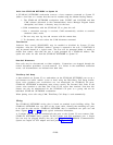
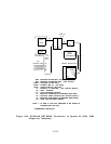
Wiring
The STARLAN NETWORK wiring plan is based on standard 4-pair building wiring. The
STARLAN NETWORK uses two pairs of the 4-pair cable, allowing the remaining two pairs
to be used for voice service.
STARLAN NETWORK data is transmitted over pairs two and
three. Figures 2-43 and 2-44 provide typical connection information.
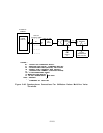
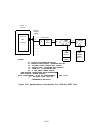
A Y-adapter may be used to combine/split the pairs at the System 25 cross-connect field.
STARLAN NETWORK NAUs provide an RJ11 phone jack that terminates pair 1. Single
line sets may be plugged directly into this jack (Figure 2-43). MERLIN Communications
System sets require an ATL adapter and local power (Figure 2-44).
2-218