


System Resources
The System Resource Circuit Packs (CP) are as follows:
● Service Circuit (ZTN85)
● Tone Detector (TN748)
● Pooled Modem (TN758).
Service Circuit (ZTN85)
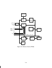
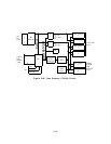
The Service Circuit CP provides the clock signals of the system. It also generates and
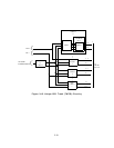
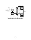
receives tones. The Service Circuit CP (Figure 3-19) consists of the following:
● Bus buffers
● Sanity and Control Interface (SAKI)
● On-board microprocessor with external RAM
● Clock circuit
● Tone generator
● Time slot table and counter
● Tone detector ports
● Port I/O and Sanity Check circuit.
The ZTN85 provides four touch-tone receivers, generates all tones for the system, and
supplies the system clocks.
The ZTN85 can support up to 75 Dual Tone Multifrequency
(DTMF) dialers depending on call traffic; the TN748s might be required in heavy traffic
situations, even with less than 75 DTMF dialers. Each System 25 must contain one Service
Circuit CP. Power for the circuit pack (+5 volts dc) is provided on the backplane.
Bus Buffers: There are four bus buffers on the circuit pack. The clock driver and receive
buffers interface three system clock signals (2.048 MHz, 8 kHz, and 160 kHz) to the TDM
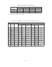
bus. Two buffers interface the system tones (see Table 3-A) between the TDM bus and the
Service Circuit CP. Music is not provided by the Service Circuit but can be provided via a
port interface on a Tip Ring Line CP (ZTN78).
SAKI: This circuit functions the same as in the SAKI in the common circuitry for the
intelligent port circuits.
On-Board Microprocessor With External RAM: This circuit functions the same as the
microprocessor in the common circuitry for the intelligent port circuits. In addition, it tells
the dual-port RAM in the time slot table circuit the appropriate time slots in which to place
a tone. The external RAM also has work space for complex tones (i.e., those tones that vary
with time).
Clock Circuit: The clock circuit consists of a 20.48-MHz oscillator, various dividers, and
shift registers.
The clock circuit runs independently from the rest of the Service Circuit
circuitry. The clock circuits start running when the circuit pack is first powered up and is
not controlled by the on-board microprocessor.
The output of the 20.48-MHz oscillator is fed to the clock divider. The divider divides by 10,
2560, and 128. These circuits produce the 2.048-MHz, 8-kHz, and 160-kHz clock signals,
respectively.
The clock generator feeds these signals to the clock driver/receiver bus buffer
and the tone clock. The tone clock uses these signals to synchronize the counters in the tone
3-38