


trunks. If Ground Start trunks are used, a 55A1 Ground Start Button must be provided at
each PFT set.
Only FCC registered single-line voice terminals may be used for PFT stations. Rotary sets
must be used for dial pulse PFT trunks; touch-tone sets must be used for touch-tone PFT
trunks.
In the event of a Power Failure Transfer (switch has lost power or a major fault has
occurred) a contact closure is provided to the Central Office (CO) over a dedicated pair of
wires. The CO then makes busy all DID trunks.
When power is restored, the closure is
removed and the CO restores DID service.
External alarm contacts are provided on the
front of the ETU for use as required.
Note: It is recommended that customers with Disservice make provisions with their CO to
provide this arrangement.
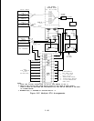
The ETUs are mounted on the cross-connect backboard.
Connections are via 25-pair
receptacle-ended (CO and SIP) and plug-ended (switch line and trunk) connectors. Modular
jacks are provided for the -48V control signal from the CPU (Call Processor Unit) and for
additional ETUs. Screw terminals are provided for the connection of external alarms.
When calculating Unit Loading (see Section 5, “Unit Loads”), all ETU loading counts against
Cabinet 1.
The 10B ETU is mounted on the cross-connect field as shown in Section 6, “Environmental
Requirements.”
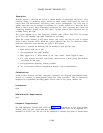
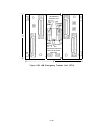
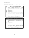
ETU Power Failure Transfer connections are shown in Figure 2-36. Part (a) on the figure
shows a single-line voice terminal that has been connected as a Power Failure Transfer
station. In normal operation, the Call Processor CP supplies -48V dc to the ETU. The voice
terminal is connected through the ETU to the station port CP and can support all calling
activities. The trunk connection through the ETU to the trunk port supports normal trunk
calls.
Part (b) on Figure 2-36 shows the ETU connections when a Power Failure Transfer has
occurred.
The transfer is initiated by the removal of the -48V dc to the ETU. All
connections through the system are dropped, and direct connections between PFT stations
and CO trunks are established. A contact closure toward the CO makes all DID trunks busy.
When the system is again able to process calls, normal service is automatically restored.
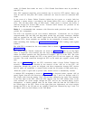
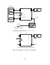
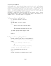
A multiple ETU arrangement is shown in Figure 2-37. As discussed earlier, separate -48V dc
control signals from the Call Processor are provided via legs 7 and 8 on Octopus cable C2.
The 25-pair cable from the Analog “Line” CP provides connectivity for eight voice terminals
at the Line input to the ETU. Since the ETU supports only five PFT stations, three of the
voice terminals are wired straight through the ETU and are not switched during service
interruptions.
A similar condition exists for the 25-pair cable (D) from the CO Trunk CP to
the Trunk input of the ETU. Three of the eight trunk port appearances are wired straight
through the ETU to the CO and are not switched. Trunk ports connected by legs 2 and 3 of
the splitter cable are wired directly to the TAE Block.
2-190