


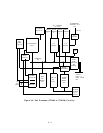
Network Controller: The network controller transmits control channel messages between
the Call Processor and the port circuits over the TDM bus.
The controller also monitors
system clocks.
The controller includes an 8-bit microprocessor that acts as a throttle passing messages
between the Call Processor and the port board microprocessors.
All uplink messages from the port circuits are checked for consistency and passed to the
Common Control. The controller is the distribution control point for all downlink control
messages.
It continuously scans, over the TDM bus, the port circuit microprocessors for
sanity and activity.
External RAM associated with this microprocessor- stores control
channel information and port related information.
The controller consists of bus buffers and a Sanity and Control Interface (SAKI). The bus
buffers provide the interface between the TDM bus and the on-board data buses to the
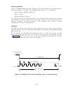
SAKI. The SAKI receives and transmits control messages on the first five time slots on the
TDM bus. The microprocessor communicates with the SAKI and external RAM over the
address and data bus.
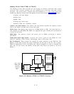
Clock: A clock provides both time-of-day information (in seconds, minutes, and hours), and
the date to the 68010. The clock automatically adjusts for leap years. An on-board battery
backs up the clock, so that accurate time is maintained even when the systern power is off.
Front Plane Interface: Dedicated buffers provide an interface to the front plane, which is
the communication path to the Memory Circuit Pack.
Reset Circuitry:
The processor is automatically reset when power is turned on, when the
+5 volt power supply drops below 4.5 volts (after it returns to +5 volts), or when the
network controller determines that the processor is not functioning correctly. The processor
can also reset the network controller when it determines that the network controller is not
functioning correctly.
Bus Error Circuitry: Bus errors suspend the processor from executing code. Bus errors
are generated when memory management detects illegal reads or writes to RAM, when the
processor attempts to access circuit packs or chips not physically present, or when the
network controller determines that the processor is not functioning correctly.
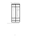
Interrupt Circuitry:
Interrupts are prioritized into seven levels, of which the highest
(leve1 7) is nonmaskable. The interrupts are:
Interrupt Level
AC Fail
7
Work cycle
6
Off board
5
EIA ports 3 and 4
4
EIA ports l and 2
3
Off board
2
Off board
1
Emergency Transfer Unit (ETU) Control: Removes -48V de power from the ETUs of
the system when the system loses power or a major system malfunction occurs.
3-4