


4-2
Cisco Unified IP Phone 8961, 9951, and 9971 Administration Guide for Cisco Unified Communications Manager 8.5 (SIP)
OL-20861-01
Chapter 4 Setting Up the Cisco Unified IP Color Key Expansion Module
Installing a Key Expansion Module on the Cisco Unified IP Phone
• Removing a Key Expansion Module, page 4-6
• Troubleshooting, page 4-6
Installing a Key Expansion Module on the Cisco Unified IP
Phone
This section contains the following topics:
• Power Information, page 4-2
• Connecting a Single KEM to the Cisco Unified IP Phone, page 4-2
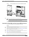
• Connecting Two or More KEMs to the Phone Using the KEM Spine Connector, page 4-3
Power Information
The Cisco Unified IP Color Key Expansion Module for the Cisco Unified IP Phone 8961, 9951, and
9971 have the following power consumption and power scheme.
Power Consumption
48V DC, 5W per KEM
Power Scheme
• At least one KEM can be powered up if the Cisco Unified IP Phone 8961, 9951, and 9971 uses AT
PoE.
• If the phone uses a power adapter, three KEMs can be powered up for the Cisco Unified
IP
Phone 9971, two KEMs can be powered up for the Cisco Unified IP Phone 9951, and one KEM
can be powered up for the Cisco Unified IP Phone 8961.
• A KEM cannot be powered up if the Cisco Unified IP Phone 8961, 9951, and 9971 uses AF PoE.
• With AT power, the Cisco Unified IP Phones 9951 and 9971 can support two KEMs plus a USB
headset or another USB device that is independently powered and only uses USB for signaling.
• The Cisco Unified IP Phone 9971 needs a power cube to support three KEMs.
• With AF power, the Cisco Unified IP Phones 9951 and 9971 need power cubes for any KEMS. The
Cisco Unified IP Phone 8961 can support one KEM with CDP, AF power, and no power cube.
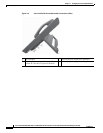
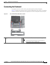
Connecting a Single KEM to the Cisco Unified IP Phone
To connect a single KEM to the Cisco Unified IP Phone, follow these steps:
Procedure
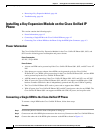
Step 1 Position the phone so that the front of the phone is facing up.
Step 2 Connect one end of the KEM spine connector to the Accessory Connector on the Cisco Unified IP Phone.
Step 3 Connect the other end of the KEM spine connector to the KEM as shown in Figure 4-1.